INSTALLATION SM15K
15 / 32 DELTA ELEKTRONIKA B.V. rev. January 2021
For sensing on a pulsating load, see paragraph 'Special
Applications' of this chapter.
5.7
The interlock connector CON F has one output (pin1) and one
input (pin3). Pin2 is not used. As soon as the link between pin
1 and 3 is interrupted, the DC power output of the unit will
shut down.
If the link is open, the interlock symbol is flashing on the
display, see fig. 5 - 11 and the interlock status will be active.
Connecting the terminals will switch the DC power terminals
on again.
Warning! The terminals can only be connected to a floating
contact, for example a switch or a relay. Internally the
terminals are connected to a logic circuit which cannot be
charged or loaded!
The current through a closed contact is less than 1mA.
The voltage over the open contact is 3.3V (typical).
It is not possible to connect the interlock of multiple SM15K
units in parallel.
With regards to safety, the Interlock connector is at the level
of Protective Earth.
On optional interface ISOLATED CONTACTS, a floating
interlock connector is available. See chapter of this manual.
The maximum Interlock wiring length is 3 meter.
5.8
BI-DIRECTIONAL OPERATION
Warning! When using the unit as a load, the user needs to
take care the voltage of the source connected to the DC
power terminals is not exceeding the maximum allowed
voltage, a too high voltage or overshoot can damage the unit.
Note that the inductance (like cable inductance) in series with
a voltage source can cause a voltage overshoot at the DC-
Power-Terminals, when switching the output from “ON” to
“OFF” or switching off the mains.
No additional hardware is needed to enable the sink current
to be delivered back into the grid.
Via the software menu the values for maximum sink current
"CC-" and sink power "POWER-" can be set.
See next paragraphs how to set up the unit for Bi-Directional
operation in combination with Series or Parallel operation.
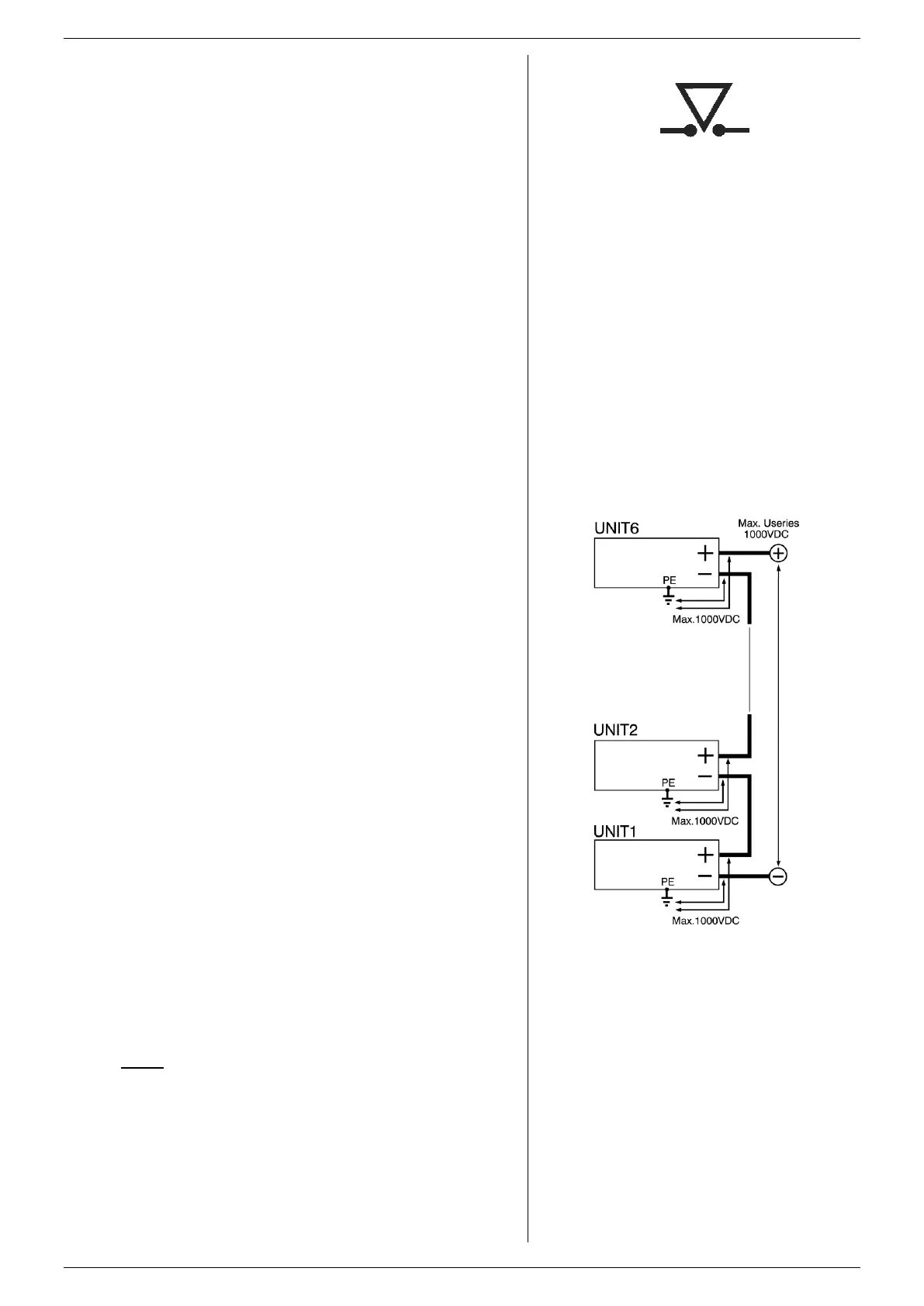
5.9
The SM500-CP-90 can be connected in series without special
precautions (see fig. 5 - 12).
Warning! Internally there is an anti-parallel diode connected
to the DC power terminals. This protects the output in case of
wrong battery connection. However in series operation it can
get overheated when current flows through the output with the
output switched to “OFF”, or the mains switched off.
To avoid overheating of the diode, take care the output is
switched to “ON” and the sink current setting CC- is sufficient
to hold the current.
The functional insulation of SM500-CP-90 allows a total
series voltage of 1000V*.
*)units delivered Q4 / 2018 or newer. Older units allow a total
series operation of max. 750V. Contact factory for upgrading
older units to enable 1000V.
Note the SM70-CP-450, SM210-CP-150 and SM1500-CP-30
cannot be connected in series.
5.10
For parallel operation without the optional M/S interface, only
one of the units can operate in Bi-Directional mode. Make
sure the CV setting of this unit is always 0.5% higher than on
the others.
For all other units disable the Bi-Directional operation by
setting the values for CC- and POWER- to 0.
fig 5 - 11
The Interlock symbol will be visible in the display
when the link is interrupted.
fig 5 - 12
For series operation of SM500-CP-90
the maximum series voltage is 1000VDC.
Take care the DC Power Terminals are floating
and the functional insulation between DC terminals
and PE is 1000VDC. This applies for both plus and
minus terminals, and for all units in series.
 Loading...


