INSTALLATION SM15K
14 / 32 DELTA ELEKTRONIKA B.V. rev. January 2021
Use cables with a diameter of 0.3 ... 0.5mm
2
and with a
sufficient voltage rating for the voltage of the circuit.
With regards to safety, the Interlock connector is at the level
of Protective Earth. For a floating Interlock contact, use the
optional interface INT MOD CON.
With firmware version P0140, all USB-connectors are
disabled.
With regards to safety, all USB are at the level of Protective
Earth.
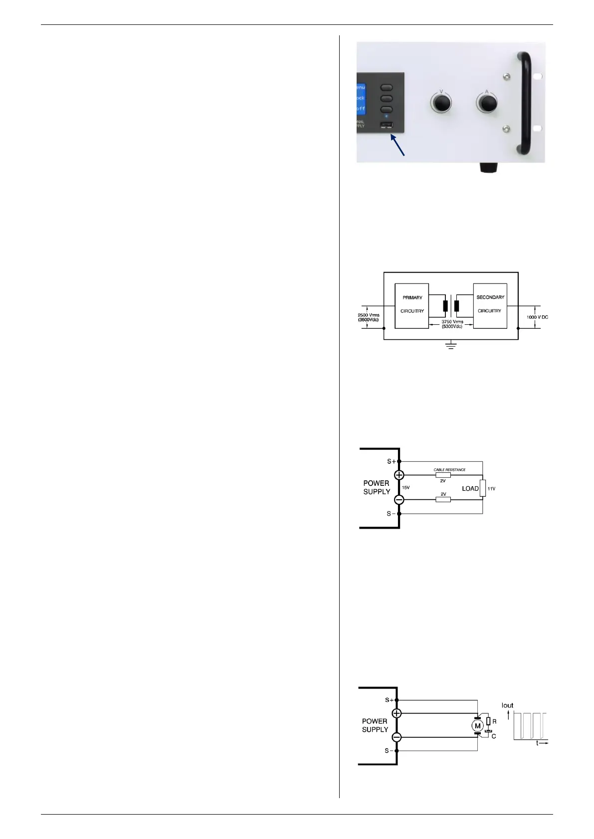
The type-A (Host) connectors are located at the front panel
near the display, and one at the rear panel (CON E), see
fig. 5 - 6 & fig. 5 - 7.
The type-B (Device) is located at the rear panel (CON G),
see fig. 5 - 6).
The type-A connectors are meant for direct connection of
flash drives for data exchange.
The type-B connector is meant for controlling the unit. Use a
cable which is maximum 3m in length.
5.4.7 OPTIONAL INTERFACES
For programming via an optional interface, refer to the
interface manual for installation and cable connections.
5.5
The insulation of the separating components between input
and output, such as transformers and opto-couplers, is tested
before assembly during 1 minute @ 3750 Vrms (5300VDC)
(see fig. 5 - 8).
The insulation between the AC terminals and Protective Earth
(3500VDC) and between DC terminals and PE (1000VDC or
1500VDC depending on unit model) is tested after assembly.
Note1: the specified insulation between AC and DC terminals
is tested at different stages during manufacturing. It cannot be
tested afterwards on the assembled unit!
Note2: when testing the insulation between the AC terminals
and PE, or the DC terminals and PE, take care to charge and
discharge the Y-capacitors slowly (e.g. in one second). This
to prevent high peak currents, which could destroy the power
supply. Make sure to discharge the Y-capacitors completely
before using it again.
5.6
Warning! This feature is not recommended for normal use,
because damping is critical and wrong connection or routing
can lead to instabilities.
With remote sensing, the voltage on the load can be kept
constant. The voltage drop in the load leads will be
compensated.
By default maximum 1 V per load lead can be compensated.
Via the web interface this can be set to maximum 10 V (see
chapter 7).
Note that the voltage drop in the leads decreases the
maximum DC output voltage rating: Uout-DC = U_leads+
Uload.
In fig. 5 - 9 it can be seen that on a 15 V power supply only
11 V will be available on the load when 2 x 2 V compensation
is used.
To minimize the inductance in the DC load leads, keep them
close to each other. The inductance of these leads could give
a problem with pulsating loads.
In this case a large electrolytic capacitor (Cd) in series with a
damping resistor (Rd) both in parallel with the load will help
(see fig. 5 - 10). Check that the capacitor Cd in combination
with the load leads and resistor Rd forms a well damped
circuit.
Since the voltmeter is internally connected to the sensing
terminals, it will automatically display the voltage on the load.
Note that the voltage measured on the load will be lower than
on the DC power terminals of the power supply.
The voltage limit setting should be increased by the total
voltage drop in the load leads.
fig 5 - 7
The location of the front USB-connector.
fig 5 - 8
Insulation test voltages.
fig 5 - 10
Remote sensing on a pulsating load.
fig 5 - 9
Remote sensing: voltage drop in DC load leads
subtracts from the maximum DC output voltage.

 Loading...


