GENERAL SM15K
9 / 32 DELTA ELEKTRONIKA B.V. rev. January 2021
The AC inrush current is electronically limited. Repeatedly
switching on and off does not change the maximum peak
current.
Switching on and off at a fast rate can overheat the inrush
current limiter with the result that the unit does not start
anymore. After cooling down (mains switched off) it will start
up again.
4.10
The efficiency is very high and constant over a wide DC sink
and source range. High efficiency means low power losses
and little heat generation.
4.11
The DC output ripple is very low with almost no spikes. At low
temperatures like -20°C the ripple increases. By using high
quality electrolytic capacitors the increase is kept to a
minimum.
4.12
Both the input and output have RFI filters, resulting in very
low conducted RFI to the line and load. Due to the output filter
the output voltage is very clean, having almost no spikes.
4.13
Digital encoders for CV and CC setting with a very long life
time and intelligent functions (e.g. Keylock, variable pitch).
Via the menu also the CP setting is done with these
encoders.
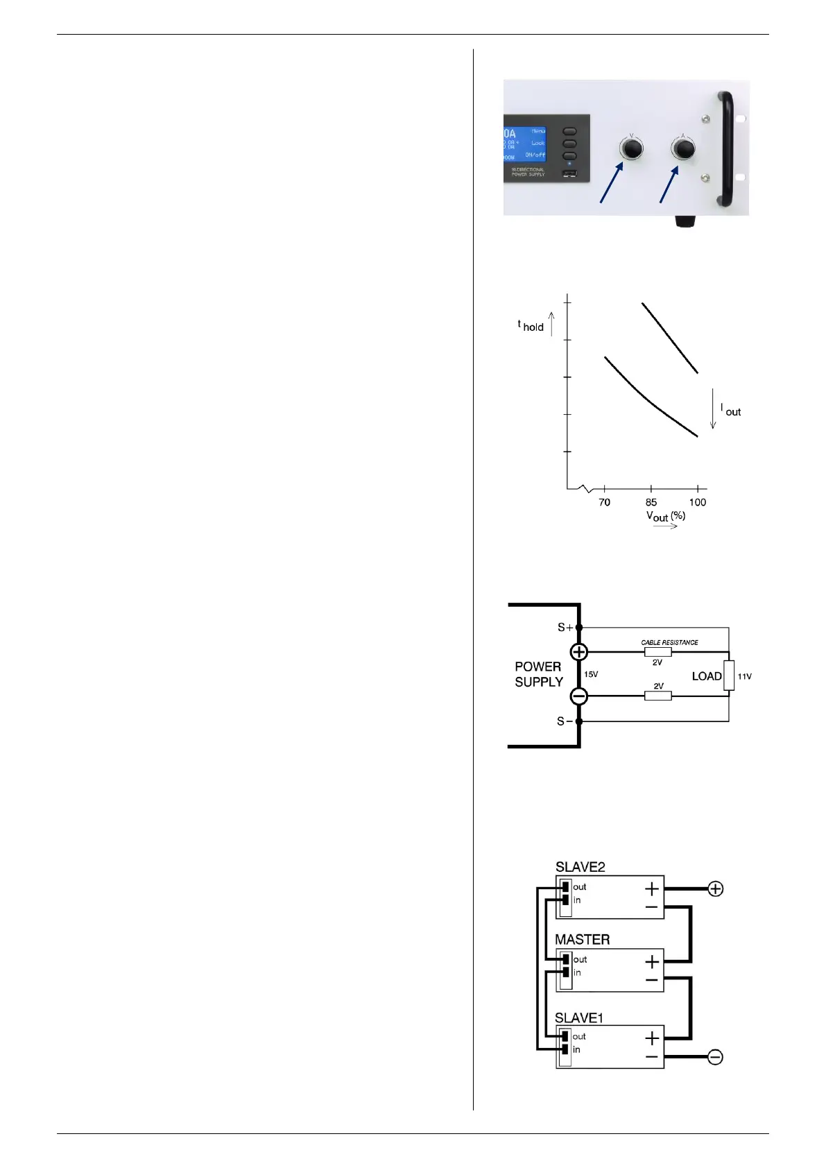
The encoders are also used for scrolling through the menu
(see fig. 4 - 2).
4.14
LIMIT FOR VOLTAGE, CURRENT and POWER
The Voltage Limit will protect your circuit from unwanted high
voltages. A high DC output voltage could be caused by
accidental interruption of leads, accidentally turning up the
voltage setting, a programming error or a defect in the
system.
The Current+ and Current- Limits protect your circuit from
unwanted high DC source and sink currents.
The Power+ and Power- Limits protect your circuit from
unwanted high sink or source power.
The Limits maintain the output to a safe preset value. They do
not trip, so no resetting is needed after a fault.
4.15
The hold - up time depends on the DC load and the DC
output voltage. A lighter load or a lower output voltage results
in a longer hold - up time (see fig. 4 - 3).
4.16
The DC voltage at the load can be kept constant by remote
sensing. This feature should only be used when the load
voltage is not allowed to vary a few millivolts.
In order to compensate for the voltage drop across the load
leads, the unit will have to supply a higher voltage (see
fig. 4 - 4).
The sense leads are protected against accidental interruption.
4.17
The power supplies can be connected in series without
special precautions. For the maximum allowed series voltage,
see chapter 'Installation'.
Warning! Note that the unit has internally an anti-parallel
diode connected to the DC power terminals, this diode can
get overheated when a larger negative current flows through
the output with the output switched to “OFF”, or the mains
switched off.
This can typically happen with units in series, where one unit
has the output switched to “OFF”. To avoid overheating of the
fig 4 - 3
Hold-up time vs. Vout with Iout as a parameter.
fig 4 - 4
Remote sensing, voltage drop in load leads
subtracts from maximum DC output.
fig 4 - 5
Optional Master / Slave series operation.
fig 4 - 2
Digital rotary encoders for voltage and current setting
and for menu operation.

 Loading...


