14
Fig. 33
Fig. 34
Fig. 35
Fig. 36
OPERATING CONTROLS AND ADJUSTMENTS
STARTING A N D
STOPPING THE SAW
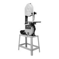
1. The on/of f switch is located under the switch shield
(A) Fig. 33. T o turn the band saw ON , move switch
trigger (B) upward to the ON position.
LOCKING SWITCH
IN T H E OFF POSITION
W e suggest that when the band saw is not in use, the
on/of f switch trigger be locked in the OFF position using
a p adlock (C) Fig. 35, through the two holes in the switch
plate, as shown in Fig. 35. NOTE: Padlock shown is
available as accessory model 50-325.
2. To turn the band saw OFF , simply push down on
the switch shield (A) Fig. 34.
TABLE INSERT
Place t able insert (A) Fig. 36, into the hole provided in
the t able surface, making cert ain the pin (B) in the t able
engages one of the indent s in the t able insert.
A
B
A
C