8
Fig. 14
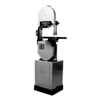
Fig. 15
Fig. 16
B
D
F
A
C
B
C
A
C
A
B
D
ASSEMBLING
M O TO R PULLEY
Assemble motor pulley (A) Fig. 14, to the motor shaf t
making cert ain set screw (B) in the motor pulley engages
with key (C) in motor shaf t.
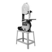
ASSEMBLING BAND SAW
TO STAND
1. Carefully place the band saw (A) Fig. 15, onto the
band saw st and (B). NOTE: Position the band saw so the
pulley (C) is over the opening (D) in the st and.
2. Align the four holes in the base of the band saw with
the four mounting holes in the top of the st and and
fasten the band saw to the st and with four 5/16-18 x
1-3/4 hex head screws, three of which are shown at (E)
Fig. 15, with flat washers and flange nut s.
ASSEMBLING AN D
ALIGNING V-BELT;
ADJUSTING BELT TENSION
1. Using a straight edge, align motor pulley (A) Fig. 16,
to the driven pulley (B). If necessary, both pulleys can be
adjusted inward or outward. The motor (C) can also be
adjusted on the motor mounting bars (D).
2. Assemble the V-belt (E) Fig. 16, to pulleys (A) and
(B) and adjust the belt tension by raising or lowering the
motor (C) on the motor mounting bars (D). If necessary,
the motor mounting bars (D) can be repositioned on two
vertical post s (F). NOTE: Make cert ain the pulleys are
kept in alignment when doing this. Correct belt tension is
obt ained when there is approximately 1 deflection, using
light finger pressure at the centersp an of the pulleys.
E
E
E