AH Motion Controller – Operation Manual
2-6
2.2 Wiring
This section introduces the connection structure and the wiring of the basic configuration with power supplies and CPUs.
For detailed wiring information including other components, please refer to AH Motion Controller
–
Hardware Manual.
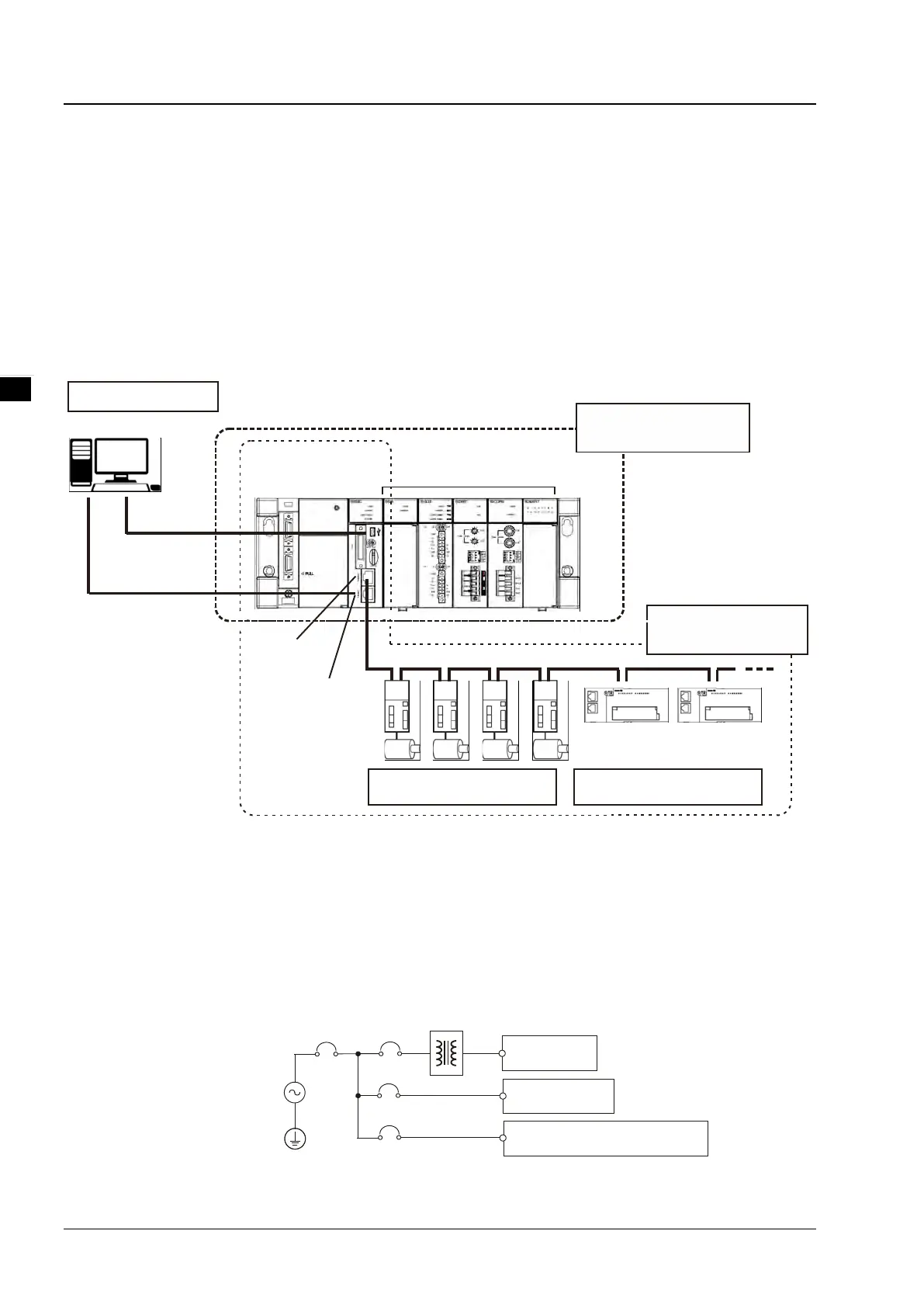
2.2.1 Basic System Configurations
The AH Motion Controller series CPU basic configurations include the AH Motion Controller CPU Network
Configuration, AH500 Series Module Configuration, and Supported Software. Refer to the below diagram for the
overview of the system connection structure.
Support Software
ISPSoft
USB(RS-232)
LAN or EtherNet/IP
AH Motion CPU
AH I/O modules
CPU
Rack
Power
Supply
Bullt-In E therNet/IP port
Bullt-In EtherCAT p ort
Servo d rives/encoder
input slaves
General-purpose slaves
EtherCAT
CPU
AH MotionNetwork
Configuration
AH500 Series Module
Configuration
2.2.2 Wiring Power Supply Modules
Precautions
Connecting AC power cables
1. Please separate the power cable of AHPS05-5A from the power cables for I/O devices and other devices. If there
is much noise, connect an isolating transformer.
AC power supply
100-240 V
AHPS05-5A
I/O equipment
Another piece of equipment
Isolating transformer

 Loading...

