Chapter 9 Troubleshooting
9-69
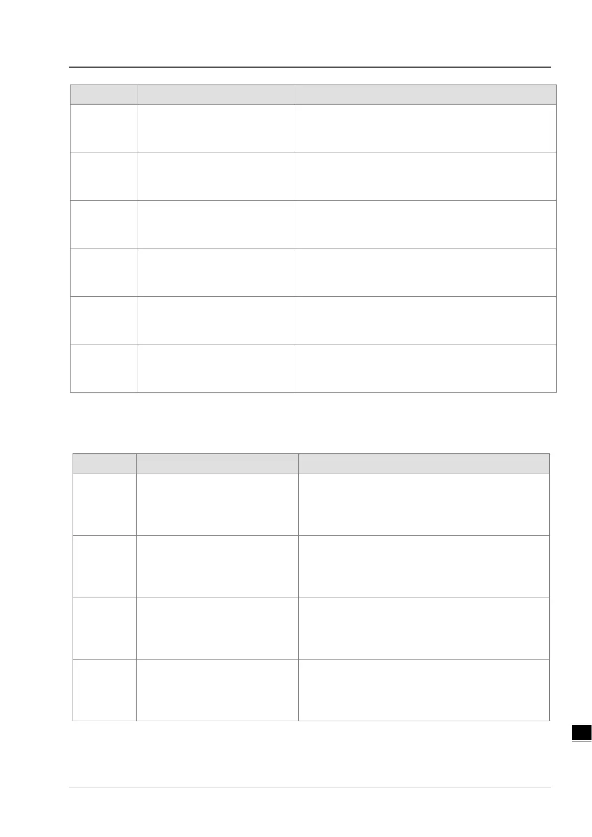
16#9B5B
COM2 receives no response from
slave 27 by MODBUS.
1. Check the communication setting between the connecting
devices.
2. Check if the communication cable is damaged.
16#9B5C
COM2 receives no response from
slave 28 by MODBUS.
1. Check the communication setting between the connecting
devices.
2. Check if the communication cable is damaged.
16#9B5D
COM2 receives no response from
slave 29 by MODBUS.
1. Check the communication setting between the connecting
devices.
2. Check if the communication cable is damaged.
16#9B5E
COM2 receives no response from
slave 30 by MODBUS.
1. Check the communication setting between the connecting
devices.
2. Check if the communication cable is damaged.
16#9B5F
COM2 receives no response from
slave 31 by MODBUS.
1. Check the communication setting between the connecting
devices.
2. Check if the communication cable is damaged.
16#9B60
COM2 receives no response from
slave 32 by MODBUS.
1. Check the communication setting between the connecting
devices.
2. Check if the communication cable is damaged.
9.4 Troubleshooting for I/O Modules
9.4.1. Analog I/O Modules and Temperature Measurement Modules
16#A000
The signal received by channel 0
exceeds the range of inputs which
can be received by the hardware.
(The ERROR LED indicator blinks.)
Check the module parameter in HWCONFIG.
Check whether the signal received by channel 0 exceeds
the range of inputs which can be received by the hardware.
16#A001
The signal received by channel 1
exceeds the range of inputs which
can be received by the hardware.
(The ERROR LED indicator blinks.)
Check the module parameter in HWCONFIG.
Check whether the signal received by channel 1 exceeds
the range of inputs which can be received by the hardware.
16#A002
The signal received by channel 2
exceeds the range of inputs which
can be received by the hardware.
(The ERROR LED indicator blinks.)
Check the module parameter in HWCONFIG.
Check whether the signal received by channel 2 exceeds
the range of inputs which can be received by the hardware.
16#A003
The signal received by channel 3
exceeds the range of inputs which
can be received by the hardware.
(The ERROR LED indicator blinks.)
Check the module parameter in HWCONFIG.
Check whether the signal received by channel 3 exceeds
the range of inputs which can be received by the hardware.
 Loading...


