Chapter 4 Installing Hardware
4-5
4.2
Wiring
4.2.1 Wiring a Power Supply Module
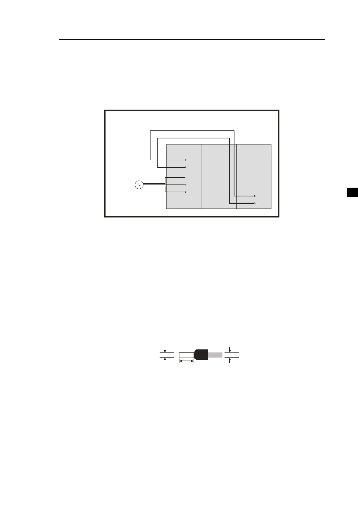
A power supply module supplies direct current to a CPU module and I/O modules.
Connecting an AC power cable
+24V
24G
LG
L
N
PS02A AS S e rie s 06XA
24V
0V
C ontrol Box
100~240V
The alternating-current input voltage is either 100 VAC or 240 VAC. Connect the power supply to the
terminals L and N. If the 110 VAC or the 220 VAC power supply is connected to the input terminals +24V
and 24G, the PLC will be damaged.
If power is interrupted for less than 10 milliseconds, the PLC keeps running without being affected. If a
power interruption lasts for longer, or if the voltage of the power supply decreases, the PLC stops running,
and there is no output. When the power supply returns to normal, the PLC resumes. Notice that there are
latched auxiliary relays and registers in the PLC when you write the program.
Use single-wire cables or two-wire cables in a diameter of 22 AWG~18 AWG and with less than 2 mm
pin-typed terminals. Only use copper conducting wires with a temperature of 60/75°C.
4.2.2 Wiring I/O Modules
The I/O modules include digital input/output, analog input/output, and network modules. Follow the directions
for the wiring of I/O modules in Chapter 5 of the AS Series Hardware Manual.
 Loading...