AS Series Operation Manual
2-59
Model
AS02HC-A
Voltage / Current
5 VDC (±5%), ±100 mA (max.)
Action
level
OFF→ON
V
ID
*1
≧ 0.2V
-
ON→OFF
V
ID
≦ 0.2V
-
Maximum input frequency
1.25 MHz
12 kΩ (terminal resistor 120 Ω)
Optocoupler
When the optocoupler is driven, the input LED indicator is ON.
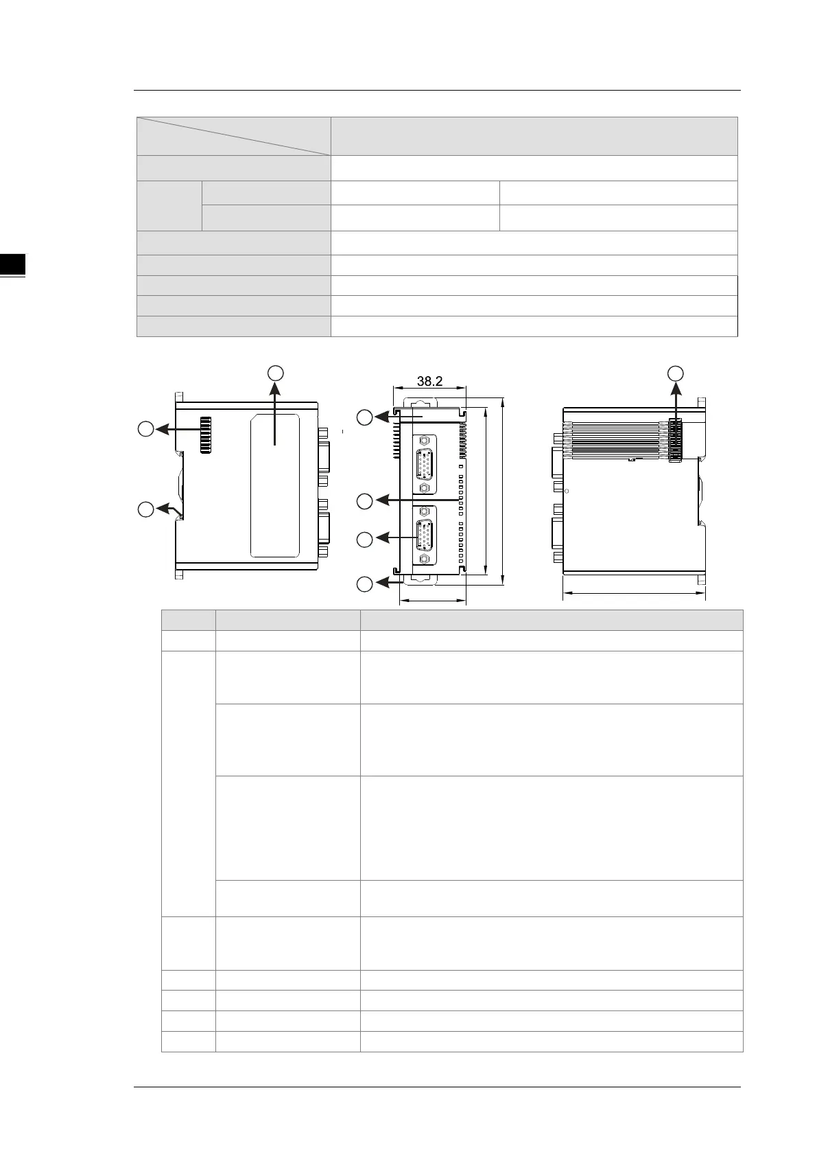
2.7.2 Counting Module Profiles
1 Model name
Model name of the module
2
POWER LED indicator
(Blue)
Indicates the status of the power supply
ON: the power is on
Error LED indicator
(Red)
Error status of the module
ON: a serious error occurs in the module.
OFF: the module is normal.
Blinking: a minor error occurs in the module.
Counter LED indicator
for Ch1 Act. & Ch2 Act.
(Green)
Counting status of the module
OFF: the counter is disabled.
ON: the counter is enabled but the result of counting is not changed.
Blinking: the result of counting is updating.
When SSI input:
Blinking: the counter is enabled and the position value is updating.
Input / output LED
ON: Receives an input / output signal
OFF: Receives no input / output signal
3 D-sub 15
Input: connected for pulse input and encoder
Output: connected to loads to be driven
Power: providing external encoder +5 VDC
Secures the module onto the DIN rail
5 Module connecting set
Connects the modules
6 Ground clip
On the DIN reail for grounding
 Loading...