ASDA-A2 Chapter 12 Absolute System
12-28 Revision February, 2017
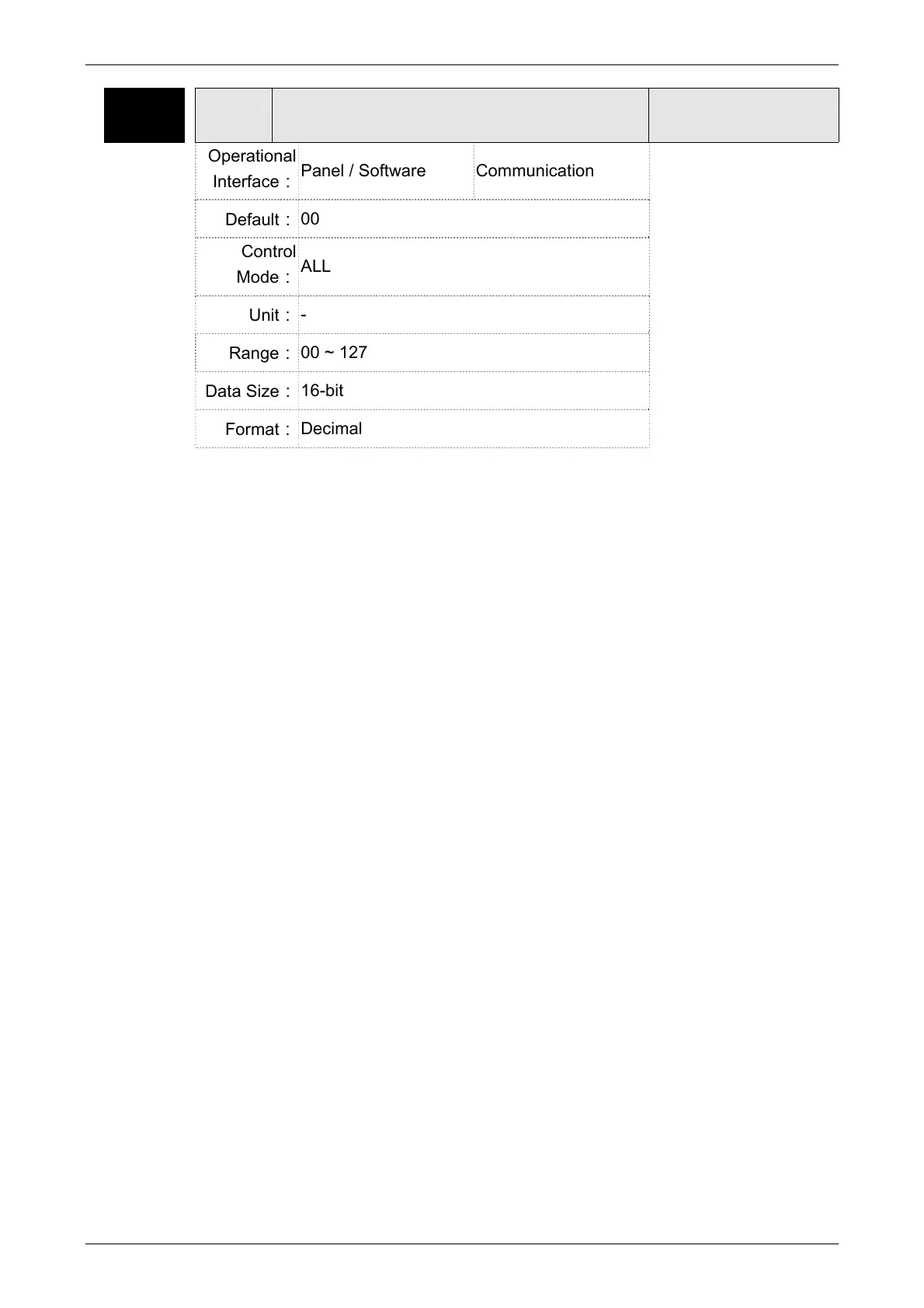
P0-02 STS Drive Status
Address: 0004H
0005H
Operational
Interface:
Panel / Software Communication
Related Section:
7.2
Default:
00
Control
Mode:
ALL
Unit:
-
Range:
00 ~ 127
Data Size:
16-bit
Format:
Decimal
Settings: 00:Motor feedback pulse number (after the scaling of electronic
gear ratio) [PUU]
01:Input pulse number of pulse command (after the scaling of
electronic gear ratio) [PUU]
02:Deviation between control command pulse and feedback pulse
number[PUU]
03:The number of motor feedback pulse [Encoder unit, 1,280,000
Pulse/rev]
04:Distance to command terminal (Encoder unit) [Pulse]
05: Error pulse number (after the scaling of electronic gear ratio)
(Encoder unit) [Pulse]
06:The frequency of pulse command input [Kpps]
07:Motor speed [r/min]
08:Speed command input [Volt]
09:Speed command input [r/min]
10:Torque command input [Volt]
11:Torque command input [%]
12:Average torque [%]
13:Peak torque [%]
14:Main circuit voltage (BUS voltage) [Volt]
15:Load/motor inertia ratio [0.1times]
16:IGBT temperature

 Loading...