Chapter 3 Wiring ASDA-A2R Series
Revision December, 2014
3-21
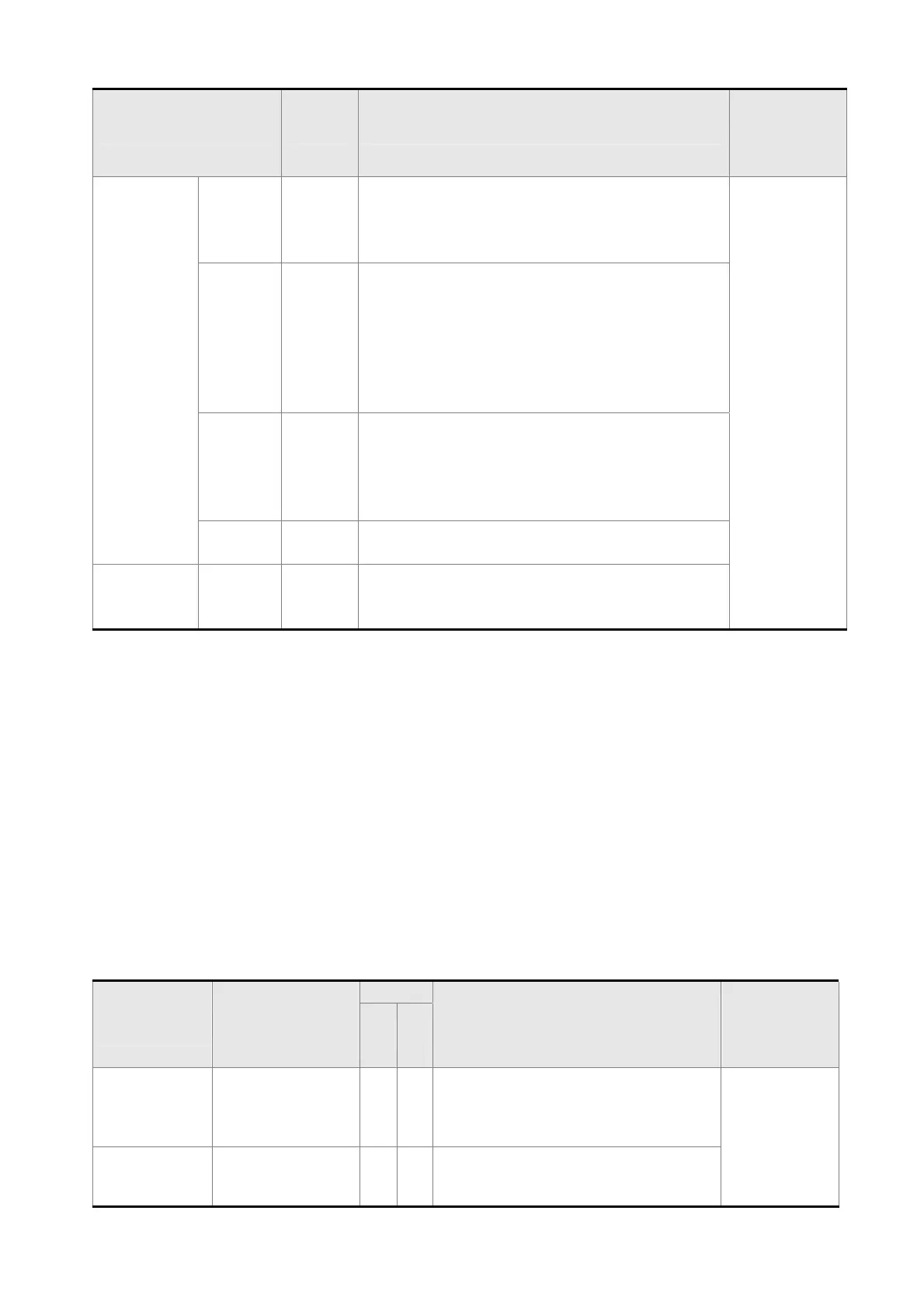
Signal Name Pin No Function
Wiring
Method
(Refer to
3.4.3)
Power
VDD 17
VDD is the +24 V power provided by the
drive and is for Digital Input (DI) and Digital
Output (DO) signal. The maximum current is
500 mA.
-
COM+
COM-
11
45
47
49
COM+ is the common input of Digital Input
(DI) and Digital Output (DO) voltage. When
using VDD, VDD should be connected to
COM+. If not using, it needs to apply the
external power (+12 V ~ + 24 V). Its positive
end should connect to COM+ and the
negative end should connect to COM-.
VCC 20
VCC is the +12V power provided by the
drive. It is used for providing the simple
analog command (speed or torque
command). The maximum current is 100
mA.
GND
12,13,
19,44
VCC voltage is based on GND.
Other NC 14
NO CONNECTION. This terminal is for
internal use only. Do not connect it, or it may
damage the servo drive.
There are numerous operation mode of this servo drive (please refer to Chapter 6.1).
Each operation mode needs different I/O signal. In order to use the terminal in a more
efficient way, the selection of I/O signal has to be programmable. That is to say, users
can choose the desired DI/DO signal to meet the demand. Basically, the default setting of
DI/DO signal has already have the appropriate function which can satisfy the demand of
normal application.
Users have to select the operation mode based on the needs first (please refer to
Chapter 6.1 for the introduction of each mode) and refer to the following DI/DO table to
know the corresponding default setting of DI/DO signal and Pin No of the selected mode
in order to conduct the wiring.
The table below lists the default setting of DI/DO signal function and pin No:
The explanation of DO signal default setting is as the followings.
DO Signal
Name
Operation Mode
Pin No
Function
Wiring
Method
(Refer to
3.4.3)
+ -
SRDY ALL 7 6
When the servo drive applies to the
power and no alarm (ALRM) occurs
in control circuit and motor power
circuit, this DO is ON.
C5/C6/
C7/C8
SON N/A - -
When the DI.SON is ON and the
motor servo circuit can operate
smoothly, this DO is ON.
 Loading...
