ASDA-B2 Chapter 6 Control Modes of Operation
Revision May, 2018 6-7
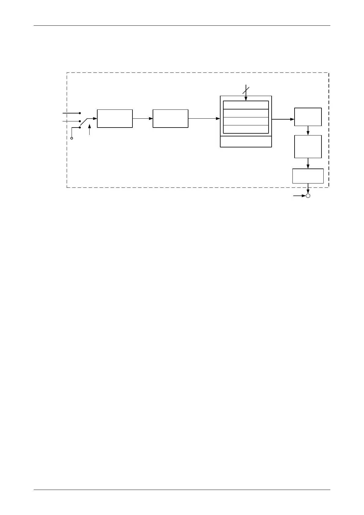
For a better control, the pulse signal should be processed and modified through position
command unit. Structure is shown as the diagram below.
Pulse Signal
Counter
1
st
Numerator (P1-44)
2
nd
Numerator (P2-60)
3
rd
Numerator (P2-61)
4
th
Numerator (P2-62)
Denominator (P1-45)
GNUM0, GNUM1
High speed
Low speed
INHIBIT
Pulse Type
Selection
P1-00
Command
Selection
P1-01
Moving
Filter
P1-68
Low-pass
Filter
P1-08
Position Command
Processing Unit
PT mode which is shown in the figure can be selected via P1-01. It can set E-gear ratio for
the proper position resolution. Moreover, either S-curve filter or low-pass filter can be used
to smooth the command. See the description in later parts.
Pulse Command Inhibit Input Function (INHP)
Use DI to select INHP (Refer to P2-10~17, P2-36 and table 7.1 INHP (45)) before using
this function. If not, this function will be unable to use. When DI (INHP) is ON, the pulse
command will be cleared in position control mode and the motor will stop running.
 Loading...

