ASDA-B2 Chapter 3 Wiring
Revision May, 2018 3-21
Users have to select the operation mode based on the needs first (please refer to Chapter
6.1 for the introduction of each mode) and refer to the following DI/DO table to know the
corresponding default setting of DI/DO signal and Pin No of the selected mode in order to
conduct the wiring.
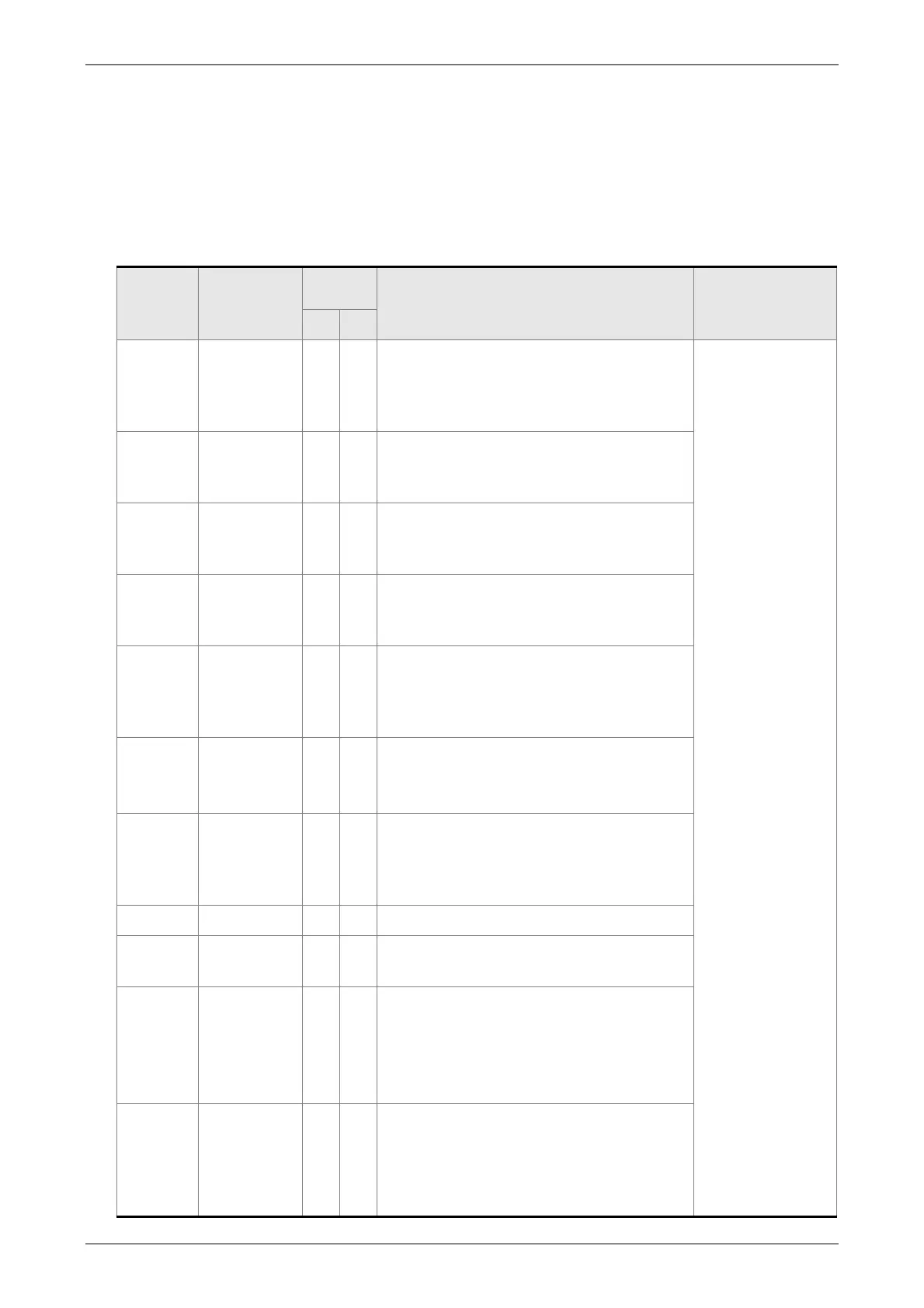
The table below lists the default setting of DI/DO signal function and pin No:
The explanation of DO signal default setting is as the followings.
DO
Signal
Operation
Mode
Pin No.
Details
Wiring Method
(Refer to 3.3.3)
+ -
SRDY ALL 7 6
When the servo drive applies to the
power and no alarm (ALRM) occurs in
control circuit and motor power circuit,
this DO is ON.
C5 / C6 / C7 / C8
SON N/A - -
When the DI.SON is ON and the motor
servo circuit can operate smoothly, this
DO is ON.
ZSPD ALL 5 4
When the motor speed is slower than
the setting value of parameter P1-38,
this DO is ON.
TSPD ALL - -
When the motor actual speed (r/min) is
faster than the setting value of
parameter P1-39, this DO is ON.
TPOS
PT, PT-S,
PT-T
1 26
When the deviation between the motor
command and actual position (PULSE)
is smaller than the setting value of
parameter P1-54, this DO is ON.
TQL
ALL
(except for
T and Tz)
- - When torque is limiting, this DO is ON.
ALRM ALL 28 27
When the alarm occurs (except
forward/reverse limit, emergency stop,
communication error, under voltage),
this DO is ON.
BRKR ALL - - Control contact of brake.
OLW ALL - -
When the overload level is reached,
this DO is ON.
WARN ALL - -
A warning occurs.
When it is in the status of forward /
reverse limit, emergency stop,
communication error, under voltage,
this DO is ON.
S_CMP S, Sz - -
When the deviation between the speed
command and the feedback speed of
the motor is smaller than the setting
value of parameter P1-47, this DO is
ON.
 Loading...

