Chapter 8 Option Cards CFP2000
8-3
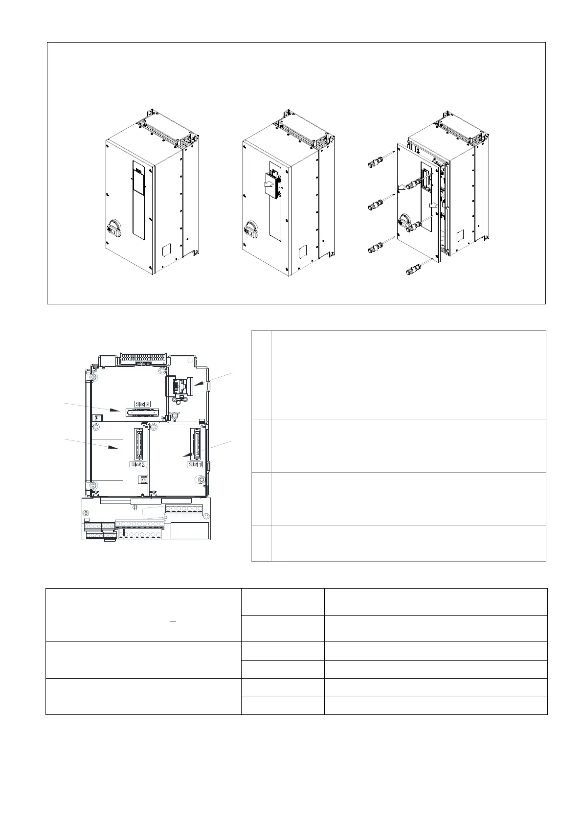
Frame D0–D
Screw Torque: 14–16 kg-cm / [12.1–13.9 lb-in.] / [1.4–1.6 Nm]
1. Remove the keypad (as shown in below figure 2).
2. Loosen the screws, then remove the top cover (as shown in below figure 3).
8-1-2 Location to Install Extension Card
Slot 1
Slot 3
Slot 2
1 RJ45 (Socket) for digital keypad KPC-CC01
Please refer to Section 10 for more details on digital
keypad.
Please refer to Section 10 for more details on optional
accessory RJ45 extension cable.
2 Communication extension card (Slot 1)
CMC-PD01; CMC-DN01; CMC-EIP01; EMC-COP01;
CMC-PN01
3 I/O & Relay extension card (Slot 3)
EMC-D42A; EMC-D611A; EMC-A22A; EMC-R6AA;
EMC-BPS01
4 PG Card (Slot 2)
※CFP2000 does not support PG card.
Screws Specification for option card terminals:
EMC-D42A; EMC-D611A
; EMC-BPS01
Wire gauge 0.2–0.5 mm
2
[26–20 AWG ]
Torque
5 kg-cm / [4.4 Ib-in.] / [0.5 Nm]
EMC-R6AA
Wire gauge
0.2–0.5 mm
2
[26–20 AWG ]
Torque
8 kg-cm / [7 Ib-in.] / [0.8 Nm]
EMC-A22A
Wire gauge
0.2–4 mm
2
[24–12 AWG]
Torque
5 kg-cm / [4.4 lb-in] / [0.5 Nm]
Figure 1 Figure 2 Figure 3
○
1
○
2
○
3
○
4



 To Next Page