Chapter 5 Main Circuit TerminalsCFP2000
5-4
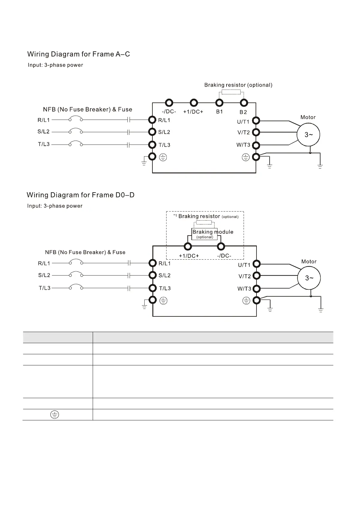
5-1 Main Circuit Diagram
Figure 5-3
*1 Please refer to Section 7-1 for brake units and resistors selection. Figure 5-4
Terminals Descriptions
R/L1, S/L2, T/L3 AC line input terminals 3-phase
U/T1, V/T2, W/T3 AC drive output terminals for connecting 3-phase induction motor
+1/DC+, -/DC-
Connections for brake module (VFDB series)
(≤ 30 kW, built-in brake module)
Common DC bus
B1, B2 Connections for brake resistor (optional)
Earth connection, please comply with local regulations.
Table 5-1