Chapter 7 Optional Accessories CFP2000
7-2
The optional accessories listed in this chapter are available upon request. Installing additional
accessories to your drive would substantially improve the drive’s performance. Please select an
applicable accessory according to your need or contact the local distributor for suggestion.
7-1 Brake Resistors and Brake Units Used in AC Motor Drives
Applicable
Motor
125%Braking Torque 10%ED*
1
Max. Brake Torque*
2
HP kW
Braking
Torque
[kg-m]
Brake
Unit
Braking Resistor Series for Each
Brake Unit*
3
Resistor Value
Spec. for Each
AC Motor
Drive
Total
Braking
Current [A]
Min.
Resistor
Value [Ω]
Max.
Total
Braking
Current
[A]
Peak
Power
[kW]
VFDB*
4
P/N Q’ty Usage
1 0.75 0.5 -
BR080W750 1 - 80W750Ω 1 190.0 4 3.0
2 1.5 0.5 -
BR080W750 1 - 80W750Ω 1 190.0 4 3.0
3 2.2 1.0 -
BR200W360 1 - 200W360Ω 2.1 126.7 6 4.6
5 3.7 1.5 -
BR300W250 1 - 300W250Ω 3 108.6 7 5.3
5 4.0 2.5 -
BR400W150 1 - 400W150Ω 5.1 84.4 9 6.8
7.5 5.5 2.7 -
BR1K0W075 1 - 1000W75Ω 10.2 54.3 14 10.6
10 7.5 3.7 -
BR1K0W075 1 - 1000W75Ω 10.2 54.3 14 10.6
15 11 5.1 -
BR1K0W075 1 - 1000W75Ω 10.2 47.5 16 12.2
20 15 7.4 -
BR1K5W043 1 - 1500W43Ω 17.6 42.2 18 13.7
25 18 10.2 -
BR1K0W016 2 2 series 2000W32Ω 24 26.2 29 22.0
30 22 12.2 -
BR1K0W016 2 2 series 2000W32Ω 24 23.0 33 25.1
40 30 14.9 -
BR1K5W013 2 2 series 3000W26Ω 29 23.0 33 25.1
50 37 20.3 -
BR1K0W016 4
2 parallel,
2 series
4000W16Ω 47.5 14.1 54 41.0
60 45 25 4045*1
BR1K2W015 4
2 parallel,
2 series
4800W15Ω 50 12.7 60 45.6
75 55 30.5 4045*1
BR1K5W013 4
2 parallel,
2 series
6000W13Ω 59 12.7 60 45.6
100 75 37.2 4030*2
BR1K0W5P1 4 4 series 8000W10.2Ω 76 9.5 80 60.8
125 90 50.8 4045*2
BR1K2W015 4
2 parallel,
2 series
9600W7.5Ω 100 6.3 120 91.2
Table 7-1
*
1
Calculation for 125% brake torque: (kW)*125%*0.8; where 0.8 is motor efficiency.
Because of the limited resistor power, the longest operation time for 10%ED is 10 seconds (ON: 10 sec. / OFF: 90 sec.).
*
2
Refer to Chapter 7 “Brake Module and Brake Resistors” in application manual for “Operation Duration & ED” vs. “Braking
Current”.
*
3
For heat dissipation, a resistor of 400 W or lower should be fixed to the frame and maintain the surface temperature below
250°C; a resistor of 1000 W and above should maintain the surface temperature below 350°C.
*
4
The calculation of the braking resistor is based on a four-pole motor (1800 rpm). Refer to VFDB series Braking Module
Instruction for more details on the braking resistor.
NOTE
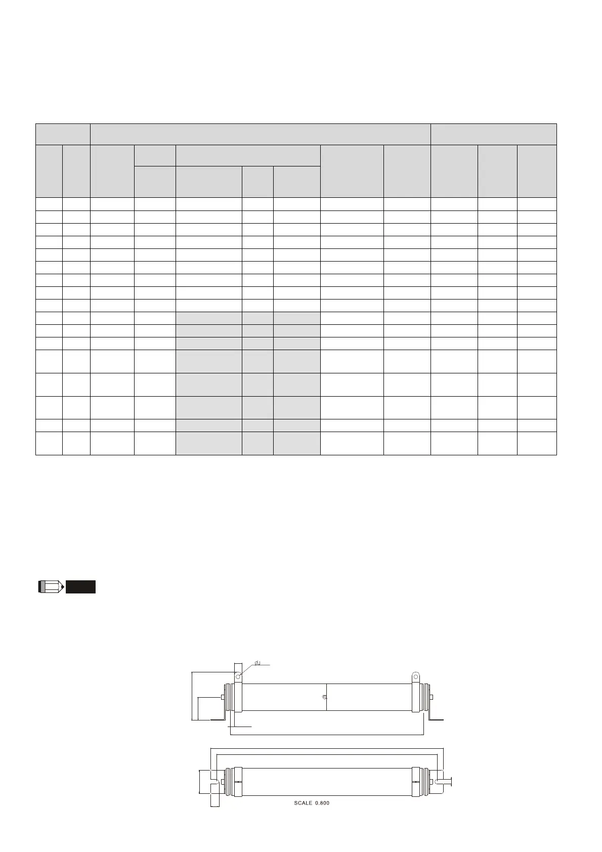
1. Specification and Appearances of Brake Resistors
1-1 Wire wound resistors:
For 1000W and above, refer to the following appearance of wire wound resistor
(Figure 7-1) and its model and specification comparison table (Table 7-2) for details.
A
B
C
D
H
F
K
G
E
L
Figure 7-1