Chapter 12 Description of Parameter SettingsCFP2000
12.1-01-2
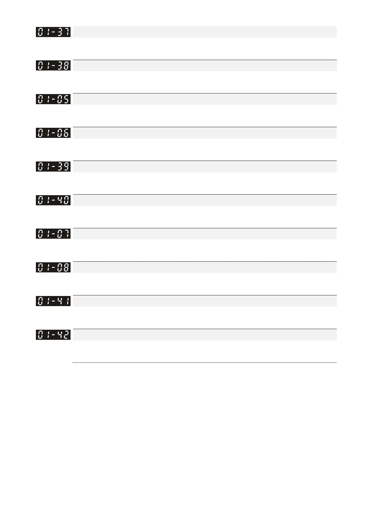
Mid-point Frequency 1 of Motor 2
Default: 3.00
Settings 0.00–599.00 Hz
Mid-point Voltage 1 of Motor 2
Default: 22.0
Settings 0.0–480.0 V
Mid-point Frequency 2 of Motor 1
Default: 1.50
Settings 0.00–599.00 Hz
Mid-point Voltage 2 of Motor 1
Default: 10.0
Settings 0.0–480.0 V
Mid-point Frequency 2 of Motor 2
Default: 1.50
Settings 0.00–599.00 Hz
Mid-point Voltage 2 of Motor 2
Default: 10.0
Settings 0.0–480.0 V
Min. Output Frequency of Motor 1
Default: 0.50
Settings 0.00–599.00 Hz
Min. Output Voltage of Motor 1
Default: 2.0
Settings 0.0–480.0 V
Min. Output Frequency of Motor 2
Default: 0.50
Settings 0.00–599.00 Hz
Min. Output Voltage of Motor 2
Default: 2.0
Settings 0.0–480.0 V
The V/F curve setting is usually set by the motor’s allowable loading characteristics. If the loading
characteristics exceeds the loading limit of the motor, you must pay more attention to the heat
dissipation, dynamic balance, and bearing lubrication of the motor.
If the voltage is too high when the motor is at low frequencies, it may cause motor damage,
overheating, and may trigger stalling or over-current protection. To prevent motor damage or
motor fault, be careful when you set the voltage.
Pr.01-35 to Pr.01-42 is the V/F curve for the motor 2. When multi-function input terminals
Pr.02-01–02-08 and Pr.02-26–Pr.02-31 are set to 14 and enabled, the AC motor drive will act as
the 2
nd
V/F curve.
The diagram below shows the V/F curve for motor 1. You can also find the V/F curve for motor 2
from the same diagram.



 To Next Page