4
Chapter 2 Control Wiring
Chapter 2 Control Wiring
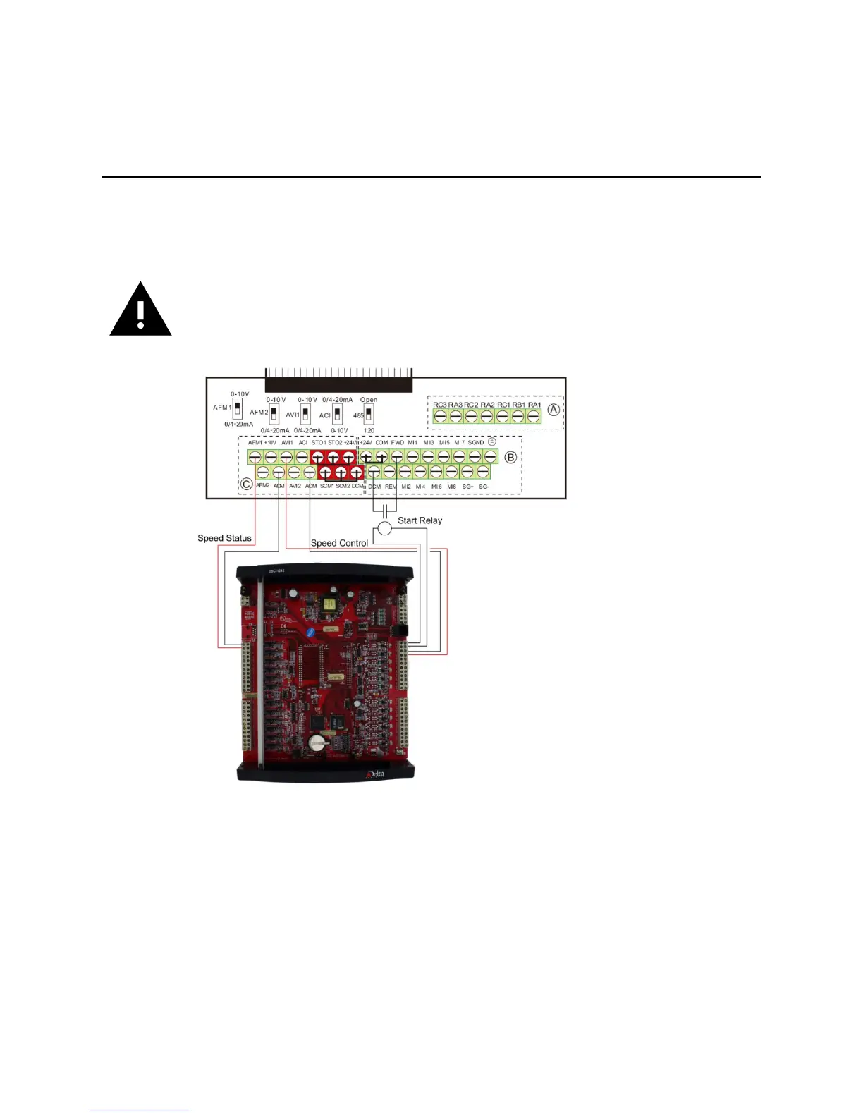
Do not remove the factory jumpers between STO1/STO2/+24V and
SCM1/SCM2/DCM.
Make sure the AFM1 and AVI1 switches are in the 0-10V position.
Make sure the Start Relay shown is not in a closed state when the drive is initially
powered up.
For the conventional start/stop, speed control and speed feedback via hard-wired I/O, the
following wiring terminations are required:
• Start/Stop: Control relay contacts wired between FWD and DCM.
• Speed Control: 0-10V speed control is connected to AVI1 (+) and ACM (-).
• Speed Feedback: 0-10V speed status is connected to AFM (+) and ACM (-).
2-1 Cabling
The analog speed signals should be using shielded cable.

 Loading...