Chapter 2 InstallationCP2000
2-4
Frame A
VFD007CP23A-21; VFD007CP43A/4EA-21; VFD015CP23A-21; VFD015CP43B/4EB-21;
VFD022CP23A-21; VFD022CP43B/4EB-21; VFD037CP23A-21; VFD037CP43B/4EB-21;
VFD040CP43A/4EA-21; VFD055CP23A-21; VFD055CP43B/4EB-21; VFD075CP43B/4EB-21;
VFD015CP53A-21; VFD022CP53A-21; VFD037CP53A-21
Frame B
VFD075CP23A-21; VFD110CP23A-21; VFD110CP43B/4EB -21; VFD150CP23A-21;
VFD150CP43B/4EB -21; VFD185CP43B/4EB -21; VFD055CP53A-21; VFD075CP53A-21;
VFD110CP53A-21; VFD150CP53A-21
Frame C
VFD185CP23A-21; VFD220CP23A-21; VFD220CP43A/4EA -21; VFD300CP23A-21;
VFD300CP43B/4EB -21; VFD370CP43B/4EB -21; VFD185CP63A-21; VFD220CP63A-21;
VFD300CP63A-21; VFD370CP63A-21
Frame D0 VFD450CP43S-00; VFD550CP43S-00; VFD450CP43S-21; VFD550CP43S-21
Frame D
VFD370CP23A-00/23A-21; VFD450CP23A-00/23A-21; VFD750CP43B-00/43B-21;
VFD900CP43A-00/43A-21; VFD450CP63A-00/63A-21; VFD550CP63A-00/63A-21
Frame E
VFD550CP23A-00/23A-21; VFD750CP23A-00/23A-21; VFD900CP23A-00/23A-21;
VFD1100CP43A-00/43A-21; VFD1320CP43B-00/43B-21; VFD750CP63A-00/63A-21;
VFD900CP63A-00/63A-21; VFD1100CP63A-00/63A-21; VFD1320CP63A-00/63A-21
Frame F
VFD1600CP43A-00/43A-21; VFD1850CP43B-00/43B-21; VFD1600CP63A-00/63A-21;
VFD2000CP63A-00/63A-21
Frame G
VFD2200CP43A-00/43A-21; VFD2800CP43A-00/43A-21; VFD2500CP63A-00/63A-21;
VFD3150CP63A-00/63A-21
Frame H
VFD3150CP43A-00/43C-00/43C-21; VFD3550CP43A-00/43C-00/43C-21;
VFD4000CP43A-00/43C-00/43C-21; VFD5000CP43A-00/43C-00/43C-21;
VFD5600CP43A-00/43C-21; VFD6300CP43A-00/43C-21; VFD4000CP63A-00/63A-21;
VFD4500CP63A-00/63A-21; VFD5600CP63A-00/63A-21; VFD6300CP63A-00/63A-21
Table 2-2
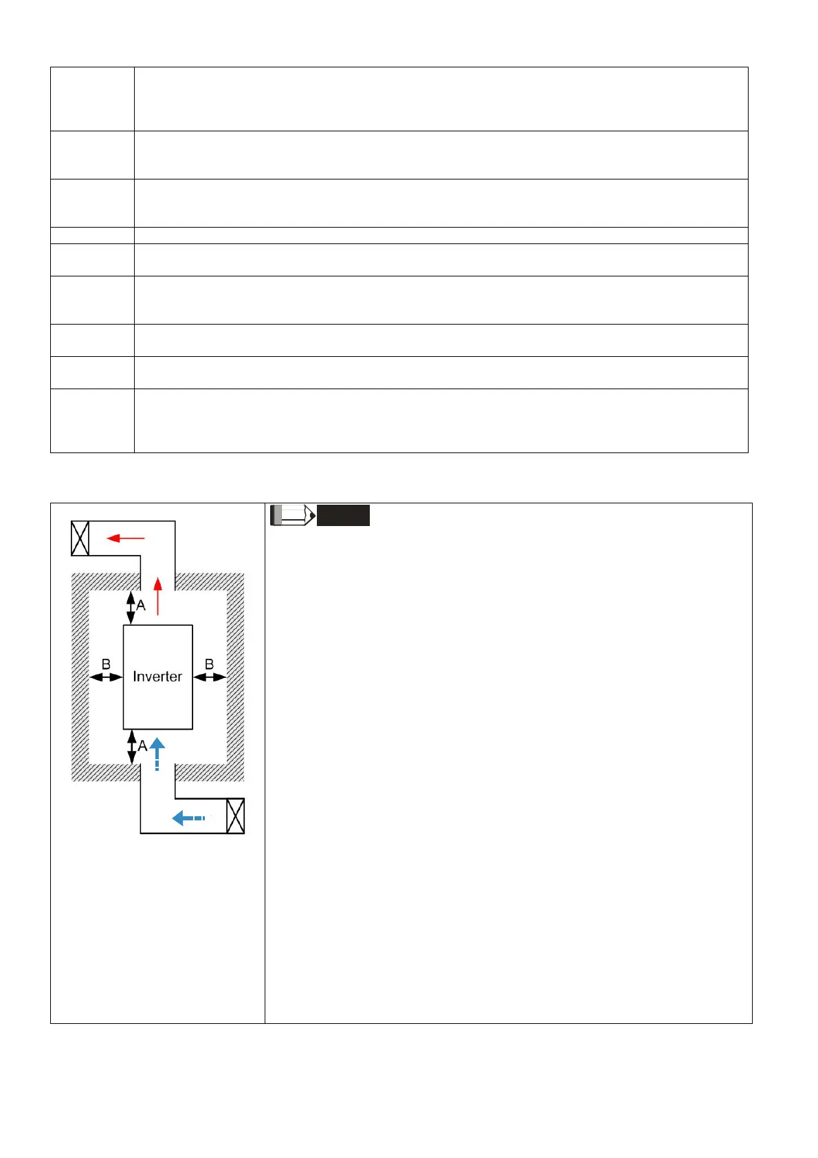
Figure 2-7
NOTE
※ The mounting clearances stated in the figure is for installing the drive in an
open area. To install the drive in a confined space (such as cabinet or
electric box), please follow the following three rules: (1) Keep the minimum
mounting clearances. (2) Install a ventilation equipment or an air
conditioner to keep surrounding temperature lower than operation
temperature. (3) Refer to parameter setting and set up Pr.00-16, Pr.00-17,
and Pr.06-55.
※ The following table shows the heat dissipation and the required air volume
when installing a single drive in a confined space. When installing multiple
drives, the required air volume shall be multiplied by the number of the
drives.
※ Refer to the chart (Air flow rate for cooling) for ventilation equipment
design and selection.
※ Refer to the chart (Power dissipation) for air conditioner design and
selection.
※ Different control mode will affect the derating. See Pr.06-55 for more
information.
※ Ambient temperature derating curve shows the derating status in different
temperature in relation to different protection level.
※ If UL Type 1 models need side by side installation, please remove top
cover of Frame A–C, and please do not install conduit box of Frame D and
above.
※ Refer to Section 9-7 for ambient temperature derating curve and derating
curves under different control mode.

 Loading...


