Chapter 16 PLC Function Applications│CP2000
16-51
Command Function
PLS
Upper differential output
Operand
X0–X17 Y0–Y17 M0–M799 T0–159 C0–C79 D0–D399
-
- - -
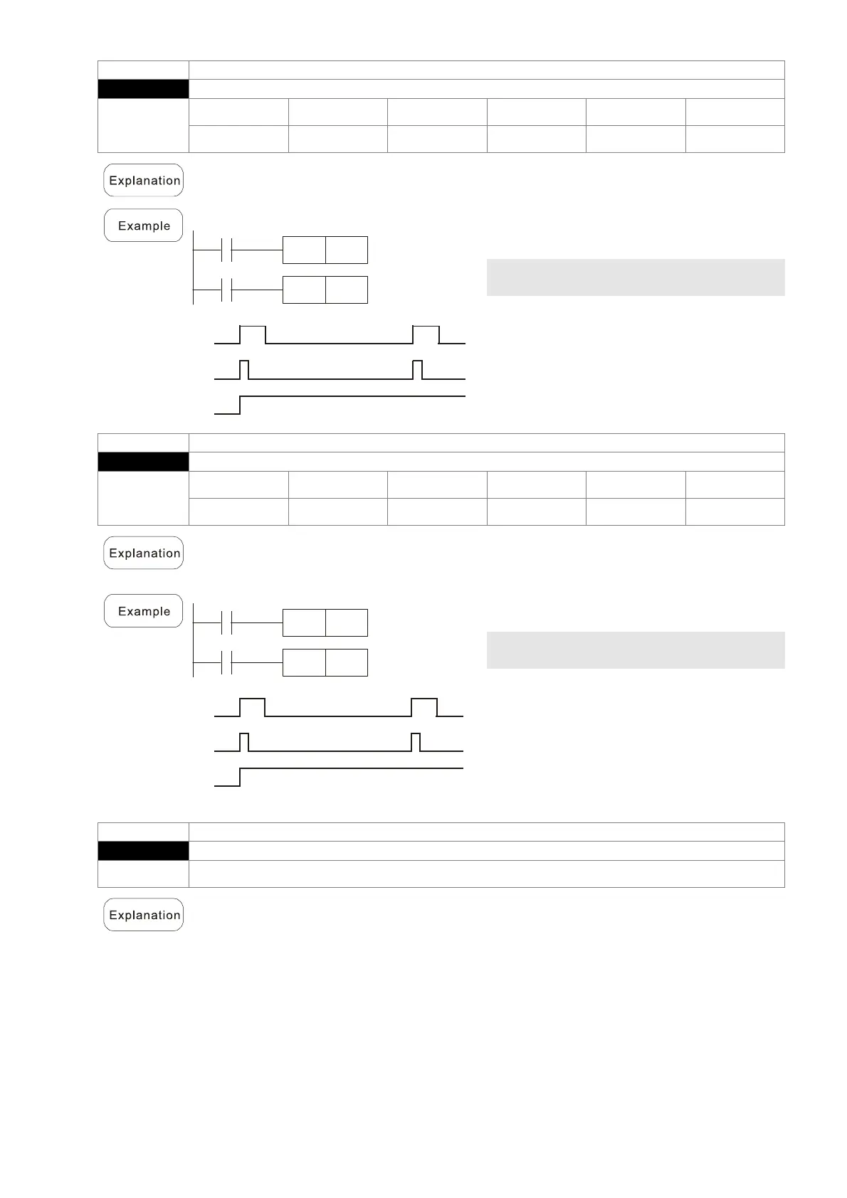
Upper differential output commands. When X0=OFF→ON (positive edge-triggered),
the PLS command will be executed, and M0 will send one pulse, with a pulse length
consisting of one scanning period.
Ladder diagram:
X0
M0
PLS
M0
Y0
SET
Time sequence diagram:
X0
M0
Y0
Time for one scan cycle
Command code: Description:
LD X0 Load Contact a of X0
PLS
M0
M0 Upper differential
output
LD M0 Load Contact a of M0
SET Y0
Y0 Action continues
(ON)
Command Function
PLF
Lower differential output
Operand
X0–X17 Y0–Y17 M0–M799 T0–159 C0–C79 D0–D399
-
- - -
Lower differential output command. When X0= On→Off (negative edge-triggered), the
PLF command will be executed, and M0 will send one pulse, with pulse length
consisting of one scanning period.
Ladder diagram:
X0
M0
PLF
M0
Y0
SET
Time sequence diagram:
X0
M0
Y0
Time for one scan cycle
Command code: Description:
LD X0 Load Contact a of X0
PLF
M0
M0 Lower differential
output
LD M0 Load Contact a of M0
SET Y0
Y0 Action continues
(ON)
Command Function
END
Program conclusion
Operand N/A
n END command must be added to the end of a ladder diagram program or
command program. The PLC will scan from address 0 to the END command, and will
return to address 0 and begins scanning again after execution.

 Loading...


