Chapter 16 PLC Function Applications│CP2000
16-102
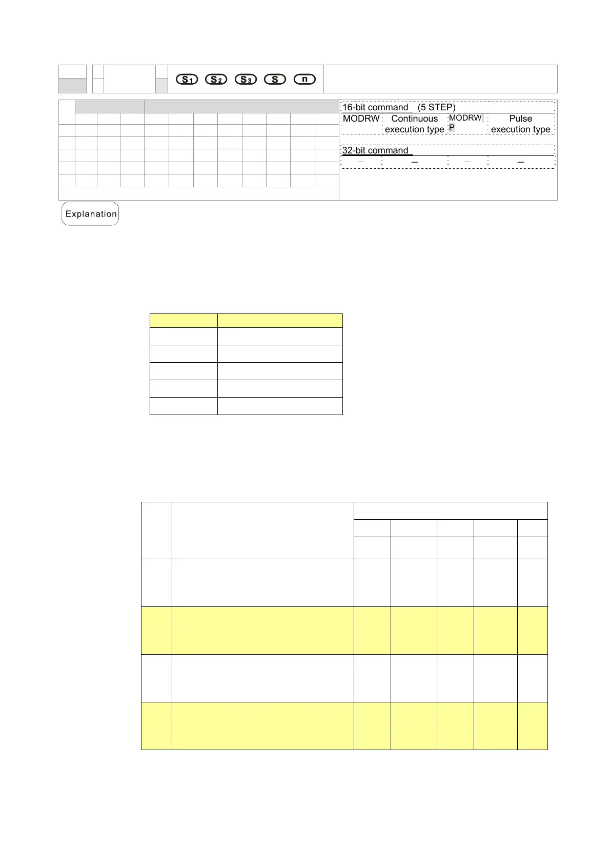
API
MODRW
Modbus data read/write
150
P
Bit device Word device
16-bit command (5 STEP)
MODRW Continuous
execution type
MODRW
P
Pulse
execution type
32-bit command
- - - -
Flag signal: M1077 M1078 M1079
X Y M K H KnX KnY KnM T C D
S1
* *
*
S2
* *
*
S3
* *
*
S
*
n
* *
*
S1: online device address. S2: communications function code. S3: address of
data to read/write. S: register for data to be read/written is stored. N: length of data
to be read/written.
COM1 must be defined as controlled by the PLC (set P9-31 = -12) before using
this command, and the corresponding communications speed and format must
also be set (set P09-01 and P09-04). S2: communications function code.
Currently only supports the following function code; the remaining function code
cannot be executed.
Function Description
H 02 Input read
H 03 Read word
H 06 Write single word
H 0F Write multiple coils
H10 Write single word
After executing this command, M1077, M1078 and M1079 will be immediately
changed to 0.
As an example, when CP2000 must control another converter and PLC, if the
converter has a station number of 10 and the PLC has a station number of 20, see
the following example:
Control slave device converter
Seria
l No.
Example
MODRW command
S1 S2 S3 S4 n
Node ID
Function
code
Address Register
Length
1
Reads 4 sets of data comprising the
converter slave device parameters
P01-00 to P01-03, and saves the read
data in D0 to D3
K10 H3 H100 D0 K4
2
Reads 3 sets of data comprising the
converter slave device addresses
H2100 to H2102, and saves the read
data in D5 to D7
K10 H3 H2100 D5 K3
3
Reads 3 sets of data comprising the
converter slave device parameters
P05-00 to P05-03, and writes the
values as D10 to D12
K10 H10 H500 D10 K3
4
Writes 2 sets of data comprising the
converter slave device addresses
H2000 to H2001, and writes the values
as D15 to D16
K10 H10 H2000 D15 K2

 Loading...


