4 Temperature Measurement Module DVP 04PT-E2
Example:
The sensor receives signals from CH1 of DVP04PT-E2. The output width of CH1 is read in CR#132, and the
output cycle of CH1 is read in CR#133. Use FROM instruction to read CR#132 and CR#133 and conduct the
cyclic control by the output width and cycle contained in GPWM instruction. Connect the heater/cooler with
PLC Y0 to execute the output.
PLC program description:
1. Read CR#132 for output width of CH1 and CR#133 output cycle of CH1. Store the obtain value in D10 and
D11.
2. Apply GPWM instruction to control the output pulse width (D10) and output cycle (D11) so as to control the
connected heater/cooler.
3. Program:
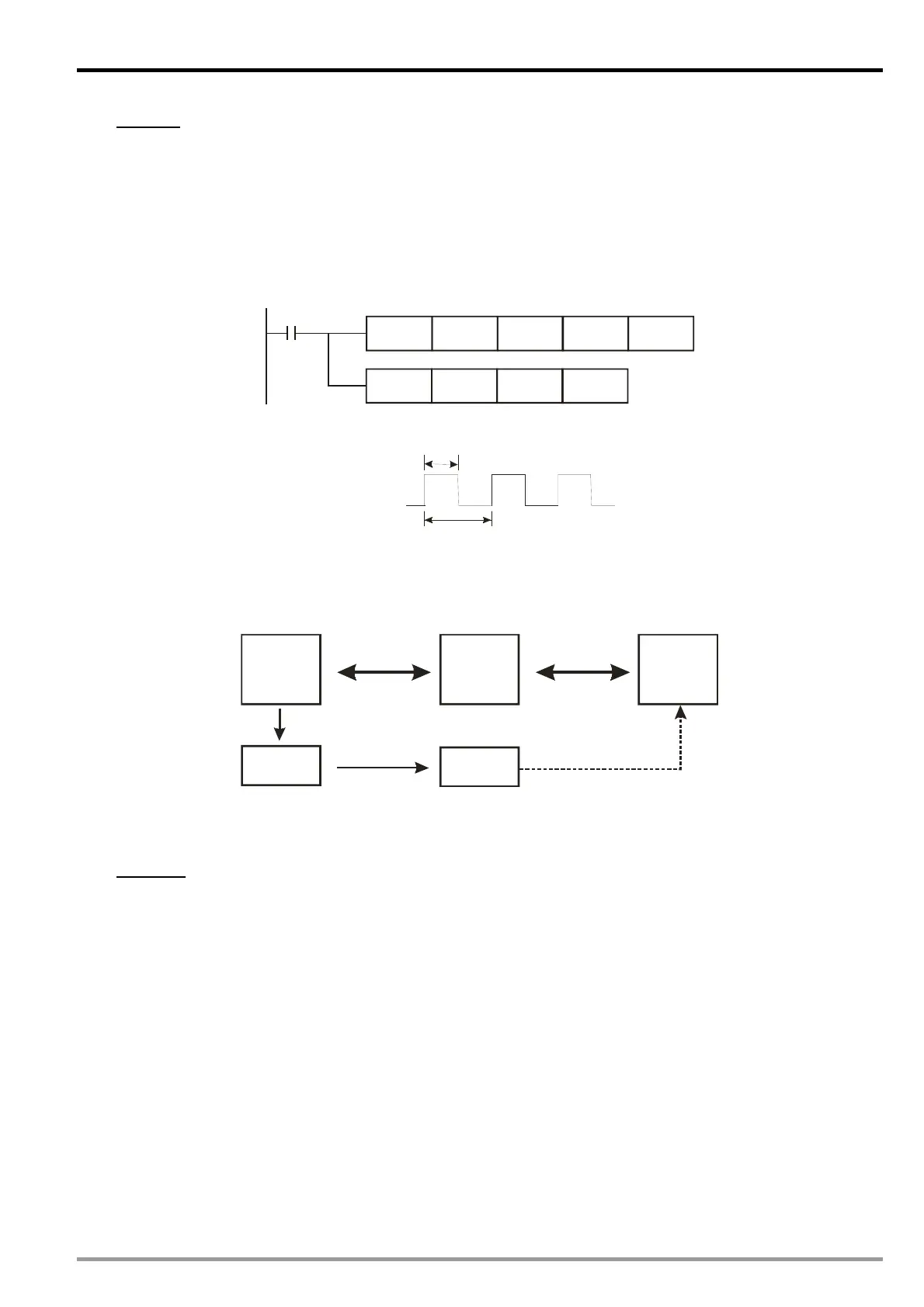
M1
FROM K0 K132 D10
K2
GPWM
D10 D11
Y0
4. Assume the pulse width is 1,000 and output cycle is 2,000, the output pulse diagram will be:
Output Y0
t=1000ms
T=2000ms
3. Analog Output Mode (CR: output volume)
If the heater or cooler you are using is controlled by voltage or current, you can read the CR which stores
digital output volume of the specified channel from DVP04PT-E2 and adopt analog output function provided by
DVP04DA-E2. Please refer to the wiring method below:
TC/PTPLC
(FROM/TO)
CR (output
volume)
Heater/
cooler
Target
temperature
D/A module
(analog
output)
(FROM/TO)
Output voltage/current
To control the heater or cooler by analog output mode, you have to set up the CR in DVP04PT-E2 which stores
the range of digital output. In addition, use FROM instruction to read the CR which stores output volume and
TO instruction to send the output volume to the analog output module.
Example:
Use the heater/cooler with DVP04DA-E2 to conduct analog output. The heater/cooler is connected to the
current output channel of DVP04DA-E2. Output range of heater/cooler: 0 ~ 32,000 (4 ~ 20mA). We set up the
upper limit (32,000) and lower limit (0) of output volume and use FROM instruction to read the digital output
value from DVP04PT-E2 to D10 and sent the content in D10 to D9910 to conduct output from DVP04DA-E2.
PLC program description:
1. Before executing the program, set CR#129 (upper limit of output volume) as 32000; CR#130 (lower limit of
output volume) as 0.
2. Read the content in CR#134 (output volume) to D10
3. Sent the value in D10 to D9910 to perform analog output.
DVP-ES2 Module Manual
-21

 Loading...


