2. Programming Concepts
Contents:
Error code for program execution
D1068
Address of program execution
error
None Unchanged Unchanged
Error code explanation:
Use of device exceeds the range (including E, F index register modification)
Square root value is negative
FROM/TO instruction communication error
D1140, D1142, D1143, D1145
Contents:
D1140: Number of right-side modules (AIO, PT, TC, etc.), max. 8 modules can be connected.
D1142: Number of input points (X) on DIO modules.
D1143: Number of output points (Y) on DIO modules.
D1145: Number of left-side modules (AIO, PT, TC, etc.), max. 8 modules can be connected.
(Only applicable for SA2/SX2/SE).
Reverse Interrupt Trigger Pulse Direction
Contents:
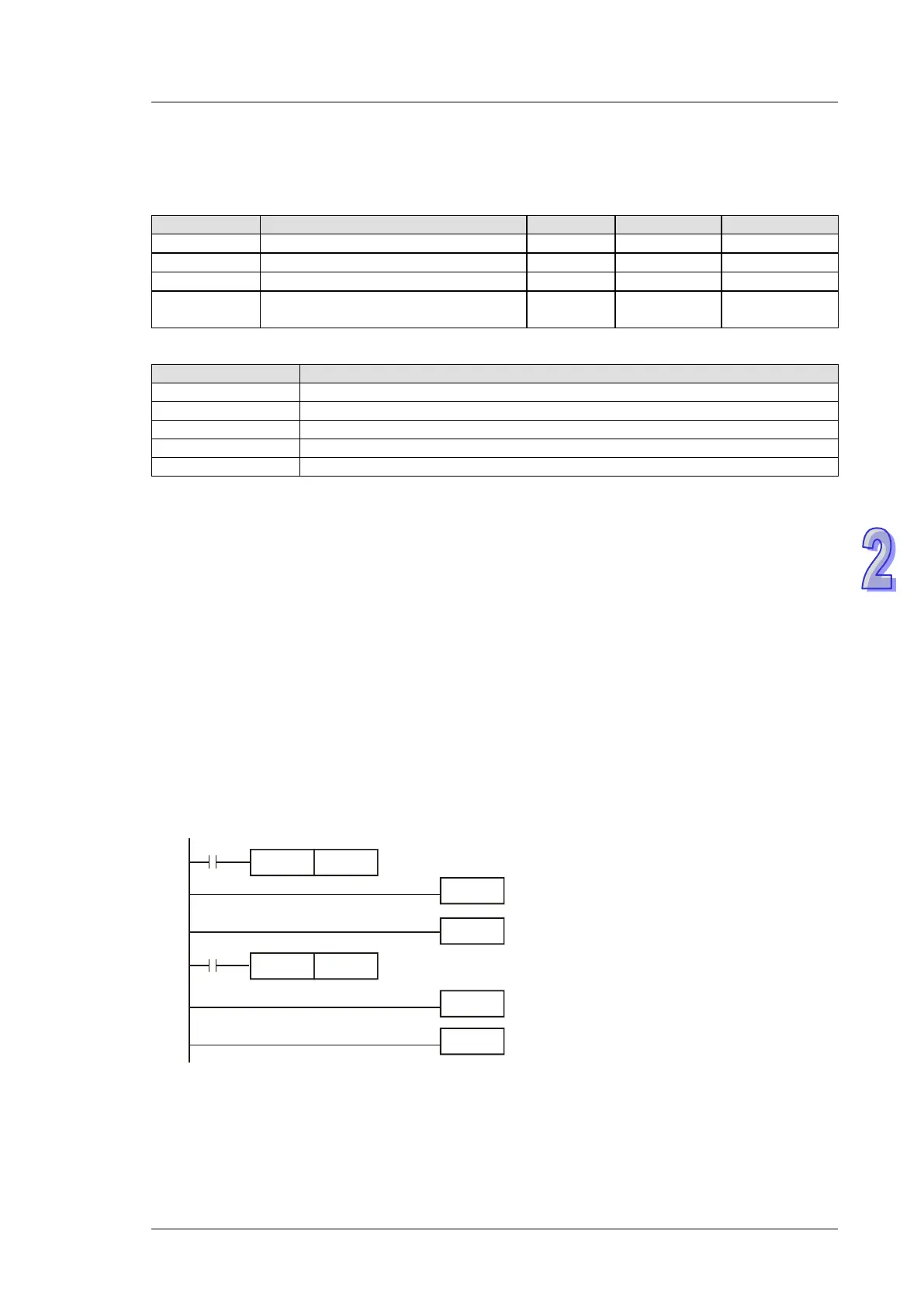
1. The falgs should be used with EI instruction and should be inserted before EI instruction
2. The default setting of interrupt I101 (X0) is rising-edge triggered. If M1280 is ON and EI
instruction is executed, PLC will reverse the trigger direction as falling-edge triggered. The
trigger pulse direction of X1 will be set as rising-edge again by resetting M1280.
3. When M0 = OFF, M1280 = OFF. X0 external interrupt will be triggered by rising-edge pulse.
4. When M0 = ON, M1280 = ON. X0 external interrupt will be triggered by falling-edge pulse.
Users do not have to change I101 to I000.
M0
OUT
M1280
EI
FEND
I001
M1000
IRET
END
INC D0