DVP-ES2/EX2/EC5/SS2/SA2/SX2/SE&TP Operation Manual - Programming
Stores Value of High-speed Counter when Interrupt Occurs
Contents:
1. If extertal interrupts are applied on input points for Reset, the interrupt instructions have the
priority in using the input points. In addition, PLC will move the current data in the counters to
the associated data registers below then reset the counters.
2. Function:
a) When X0 (counter input) and X1 (external Interrupt) correspondingly work together with
C243, and I100/I101, PLC will move the count value to D1241 and D1240.
b) When X0 (counter input) and X4 (external Interrupt) correspondingly work together with
C246, C248, C252 and I400/I401, PLC will move the count value to D1241 and D1240
c) When X2 (counter input) and X3 (external Interrupt) correspondingly work together with
C244, and I300/I301, PLC will move the count value to D1243 and D1242.
d) When X2 (counter input) and X5 (external Interrupt) correspondingly work together with
C250, C254 and I500/I501, PLC will move the count value to D1243 and D1242.
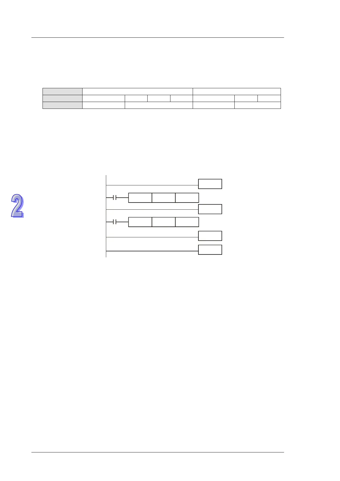
Example:
M1000
DCNT
C243 K100
EI
FEND
I101
M1000
IRET
END
DMOV
D1240 D0
When external interrupt (X1, I101) occurs during counting process of C243, the count value in
C243 will be stored in (D1241, D1240) and C243 is reset. After this, the interrupt subroutine I101
will be executed
Enabling force-ON/OFF of input point X
Contents:
When M1304 = ON, WPLSoft or ISPSoft can set ON/OFF of input pont X, but the associated
hardware LED will not respond to it.
Output specified pulses or seek Z phase signal when zero point is achieved.
Contents:
When zero point is achieved, PLC can output specified pulses or seek Z phase signal by this
function. Input terminals X2, X3 are the Z-phase signal input point of CH1, CH2. When M1308= ON,
D1312 is the setting register to specify the additional pulses within the range -30,000~30,000.
Specified value exceeds the range will be changed as the max/min value automatically. When
D1312 is set to 0, the additional pulses output function will be disabled.
Functions of other input terminals:
X4 → CH1 DOG signal input
X6 → CH2 DOG signal input
X5 → CH1 LSN signal input
X7 → CH2 LSN signal input