EasyManuals Logo

Delta DVP-EX2 User Manual

Delta DVP-EX2
1006 pages
To Next Page IconTo Next Page
To Previous Page IconTo Previous Page
Page #112 background imageLoading...
Page #112 background image
DVP-ES2/EX2/EC5/SS2/SA2/SX2/SE&TP Operation Manual - Programming
2-76
Writing complete on PLC LINK connection ID#17-24 (System resets to OFF after writing is complete on one module.)
M1504
M1505
M1506
M1507
M1508
M1509
M1510
M1511
CONNECTION
ID 17
CONNECTION
ID 18
CONNECTION
ID 29
CONNECTION
ID 20
CONNECTION
ID 21
CONNECTION
ID 22
CONNECTION
ID 23
CONNECTIO
N ID 24
Read
out
Write
in
Read
out
Write
in
Read
out
Write
in
Read
out
Write
in
Read
out
Write
in
Read
out
Write
in
Read
out
Write
in
Read
out
Write
in
D100
D115
D200
D215
D100
D115
D200
D215
D100
D115
D200
D215
D100
D115
D200
D215
D100
D115
D200
D215
D100
D115
D200
D215
D100
D115
D200
D215
D100
D115
D200
D215
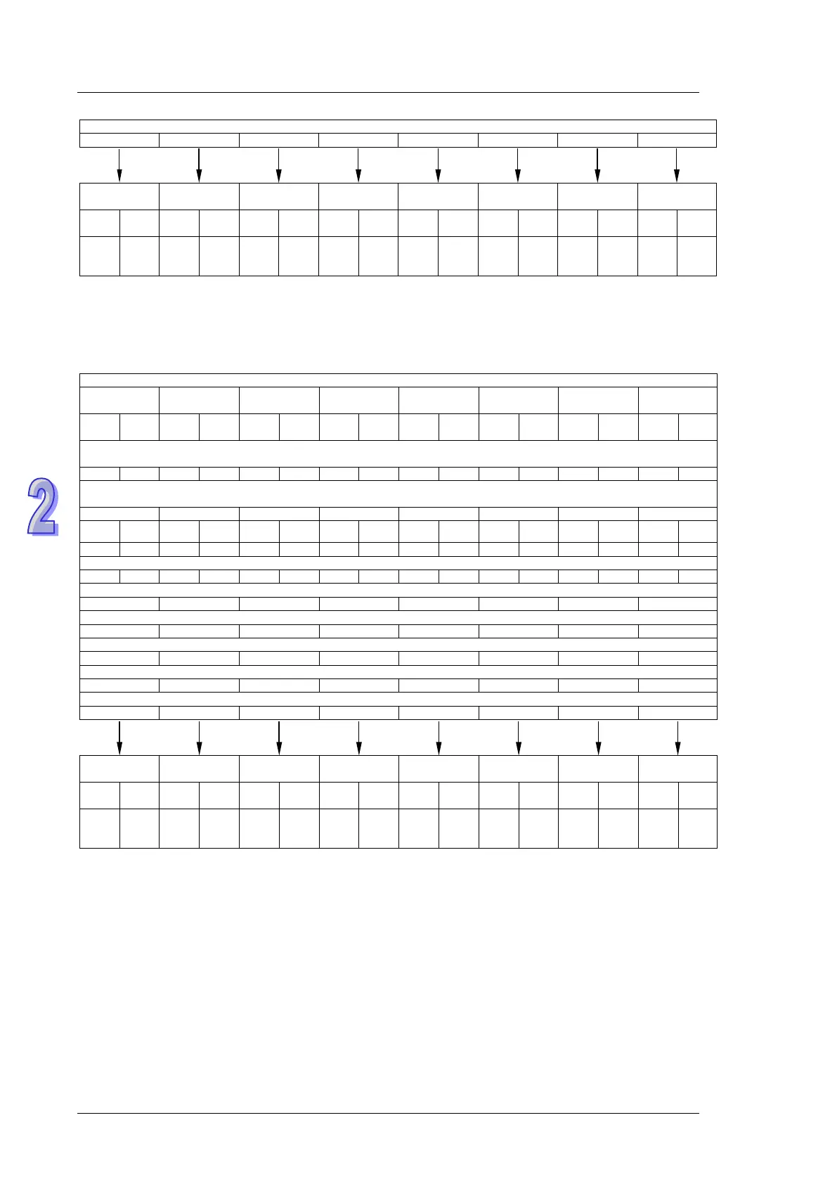
Default start communication address D1512 ~ D1519 to be read = H1064 (D100)
Default start communication address D1528 ~ D1535 to be written = H10C8 (D200)
7. Special D and special M corresponding to Connection ID25~ID32: (M1353 = ON, access
available for up to 100 words) (Mode supported: DVP-12SE V1.6 and DVP-26SE V2.0)
MASTER PLC
CONNECTION
ID 25
CONNECTION
ID 26
CONNECTION
ID 27
CONNECTION
ID 28
CONNECTION
ID 29
CONNECTION
ID 30
CONNECTION
ID 31
CONNECTIO
N ID 32
Read
out
Write
in
Read
out
Write
in
Read
out
Write
in
Read
out
Write
in
Read
out
Write
in
Read
out
Write
in
Read
out
Write
in
Read
out
Write
in
DVP-SE supports M1353. When M1353 is On, 32 stations in the Link and the function of reading/writing more than 16 data
(SET M1353) are enabled. The user can specify the starting register for storing the read/written data in registers below.
D1584
D1600
D1585
D1601
D1586
D1602
D1587
D1603
D1588
D1604
D1589
D1605
D1590
D1606
D1591
D1607
If M1356 is ON, users can set the station numbers of Connection ID25~ID32 in D1924~D1931. The master station sends
commands according to the station numbers set.
D1924
D1925
D1926
D1927
D1928
D1929
D1930
D1931
Number
of data
Number
of data
Number
of data
Number
of data
Number
of data
Number
of data
Number
of data
Number
of data
Number
of data
Number
of data
Number
of data
Number
of data
Number
of data
Number
of data
Number
of data
Number
of data
D1552
D1568
D1553
D1569
D1554
D1570
D1555
D1571
D1556
D1572
D1557
D1573
D1558
D1574
D1559
D1575
Starting address of the Connection to be read, written or connected.*
D1520
D1536
D1521
D1537
D1522
D1538
D1523
D1539
D1524
D1540
D1525
D1541
D1526
D1542
D1527
D1543
Activation status of connection ID#25-32 on PLC LINK (ON: activated)
M1448
M1449
M1450
M1451
M1452
M1453
M1454
M1455
Communication status of Connection ID#25-32 on PLC LINK (ON: communicating)
M1464
M1465
M1466
M1467
M1468
M1469
M1470
M1471
Error flag for errors occurred when reading or writing on Connection ID#25-32 (ON = normal; OFF = error)
M1480
M1481
M1482
M1483
M1484
M1485
M1486
M1487
Reading complete on PLC LINK Connection ID#25-32 (System resets to OFF after reading is complete on one module.)
M1496
M1497
M1498
M1499
M1500
M1501
M1502
M1503
Writing complete on PLC LINK connection ID#25-32 (System resets to OFF after writing is complete on one module.)
M1512
M1513
M1514
M1515
M1516
M1517
M1518
M1519
CONNECTION
ID 25
CONNECTION
ID 26
CONNECTION
ID 27
CONNECTION
ID 28
CONNECTION
ID 29
CONNECTION
ID 30
CONNECTION
ID 31
CONNECTIO
N ID 32
Read
out
Write
in
Read
out
Write
in
Read
out
Write
in
Read
out
Write
in
Read
out
Write
in
Read
out
Write
in
Read
out
Write
in
Read
out
Write
in
D100
D115
D200
D215
D100
D115
D200
D215
D100
D115
D200
D215
D100
D115
D200
D215
D100
D115
D200
D215
D100
D115
D200
D215
D100
D115
D200
D215
D100
D115
D200
D215
Default start communication address D1520 ~ D1527 to be read = H1064 (D100)
Default start communication address D1536 ~ D1543 to be written = H10C8 (D200)
8. Explanation: (up to 16 connections can be supported.)
a) PLC LINK is based on MODBUS communication protocol.
b) Baud rate and communication format of all phariferal devices connected to the Slave PLC
should be the same as the communication format of Master PLC, no matter which COM
port of Slave PLC is used.
c) When M1356 = OFF(Default), the station number of the connection ID1 can be designated
by D1399 of Master PLC through PLC LINK, and PLC will automatically assign ID2~ID16
with consecutive station numbers according to the station number of ID1. For example, if
D1399 = K3, Master PLC will send out communication commands to ID1~ID16 which carry
station number K3~K18. In addition, care should be taken when setting the station number

Table of Contents

Questions and Answers:

Question and Answer IconNeed help?

Do you have a question about the Delta DVP-EX2 and is the answer not in the manual?

Delta DVP-EX2 Specifications

General IconGeneral
BrandDelta
ModelDVP-EX2
CategoryController
LanguageEnglish

Related product manuals