3. Instruction Set
RTU
ASCII
COM1(RS-232) K 64 K 16 K 64 K 16
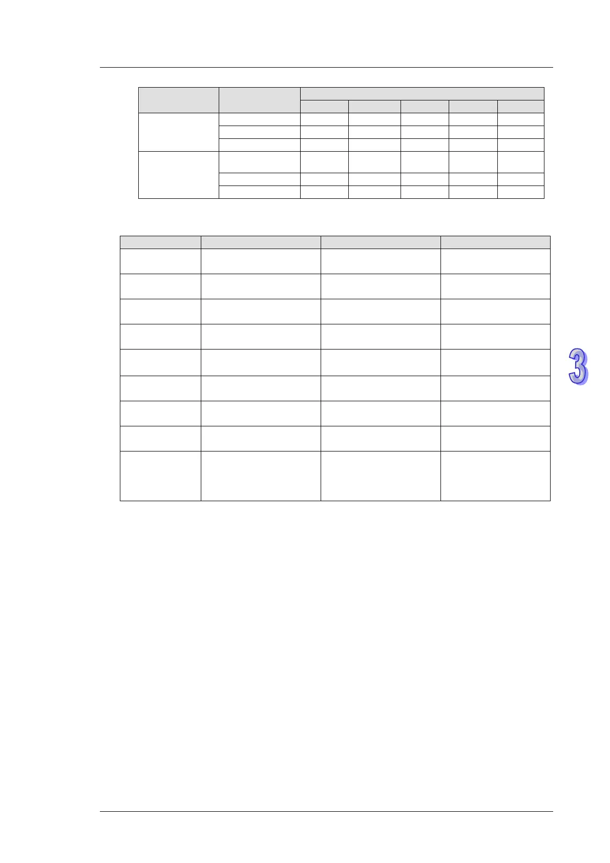
7. The functions of S
3
, S, and n vary with the function code used.
H01
Address from which the
data is read
Register in which the
data read is stored
Length of data read
H02
Address from which the
data is read
Register in which the
data read is stored
Length of data read
H03
Address from which the
data is read
Register in which the
data read is stored
Length of data read
H04
Address from which the
data is read
Register in which the
data read is stored
Length of data read
H05
Address into which the
data is written
No meaning Status value written
H06
Address into which the
data is written
Register in which the
data written is stored
No meaning
H0F
Address into which the
data is written
Register in which the
data written is stored
Length of data written
H10
Address into which the
data is written
Register in which the
data written is stored
Length of data written
H17
3
the data is read
S
3
+1: Address into
which the data is written
data read is stored
S+1: Register in which
the data written is stored
n: Length of data read
n+1: Length of data
written
8. There is no limitation on the times of using this instruction, however only one instruction can be
executed on the same COM port at a time.
9. Rising-edge contact (LDP, ANDP, ORP) and falling-edge contact (LDF, ANDF, ORF) can not be
used as drive contact of MODRW (Function code H01, H02, H03, H04, H17) instruction,
otherwise the data stored in the receiving registers will be incorrect.
10. MODRW instruction determines the COM port according to the communication request. The
COM port determination is made following the order: COM1COM3COM2. Therefore,
please insert every MODRW instruction right after the sending request instruction for avoiding
errors on the target location for data access.
11. For detailed explanation of the associated flags and special registers, please refer to Points to
note of API 80 RS instruction.