DVP-ES2/EX2/EC5/SS2/SA2/SX2/SE&TP Operation Manual - Programming
Program Example 1: COM2(RS-485), Function Code H02 (H01 is used the same as H02.)
1. Function code K2 (H02): read multiple bit devices, up to 64 bits can be read.
2. PLC1 connects to PLC2: (M1143 = OFF, ASCII mode), (M1143 = ON, RTU Mode)
3. In ASCII or RTU mode, when PLC’s COM2 sends out data, the data will be stored in
D1256~D1295. The feedback data will be stored in registers starting with S and converted into
D1296~D1311 in Hex automatically.
4. Take the connection between PLC1 (PLC COM2) and PLC2(PLC COM1) for example, the
tables below explains the status when PLC1 reads Y0~Y17 of PLC2.
H87
MOV
M1002
D1120
SET
M1120
K100
MOV
D1129
RST
M1127
Set communication protocol as 9600, 8, E, 1
Retain communication protocol
Set communication timeout as 100ms
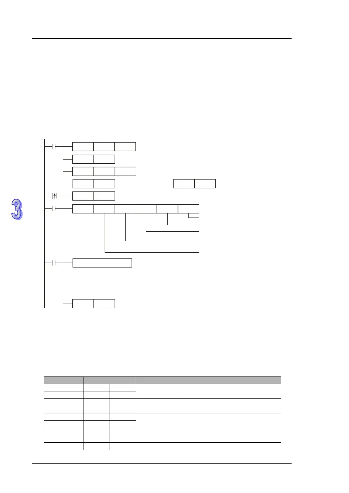
MODRW
K2
K1
X0
H0500 D0 K16
Connection device
address K1
Function code K2
read multiple bits
Data address Y0=H0500
Data storing register
Data length (bit)
Processing received data
ASCII mode: The received data is stored in registers starting from D0 in ASCII format and
PLC converts the content to hexadecimal automatically.registers D1296~D1311 in
RTU mode: The received data is stored in registers starting from D0 in Hex.
Reset M1127
M1127
SET
X0
M1122
Sending request
M1143 = OFF
ASCII mode
RST
M1143
M1143 = ON
RTU mode
SET
M1143
Receiving completed
ASCII Mode (M1143 = OFF):
When X0 = ON, MODRW instruction executes the function specified by Function Code 02.
PLC1 PLC2,PLC1 sends: “01 02 0500 0010 E8”
PLC2 PLC1,PLC1 receives: “01 02 02 3412 B5”
Registers for data to be sent (sending messages)
Device address: ADR (1,0)
Control parameter: CMD (1,0)
Y0 = H0500
Starting Data Address
Number of Data(count by bit)