DVP-ES2/EX2/EC5/SS2/SA2/SX2/SE&TP Operation Manual - Programming
Registers for received data (responding messages)
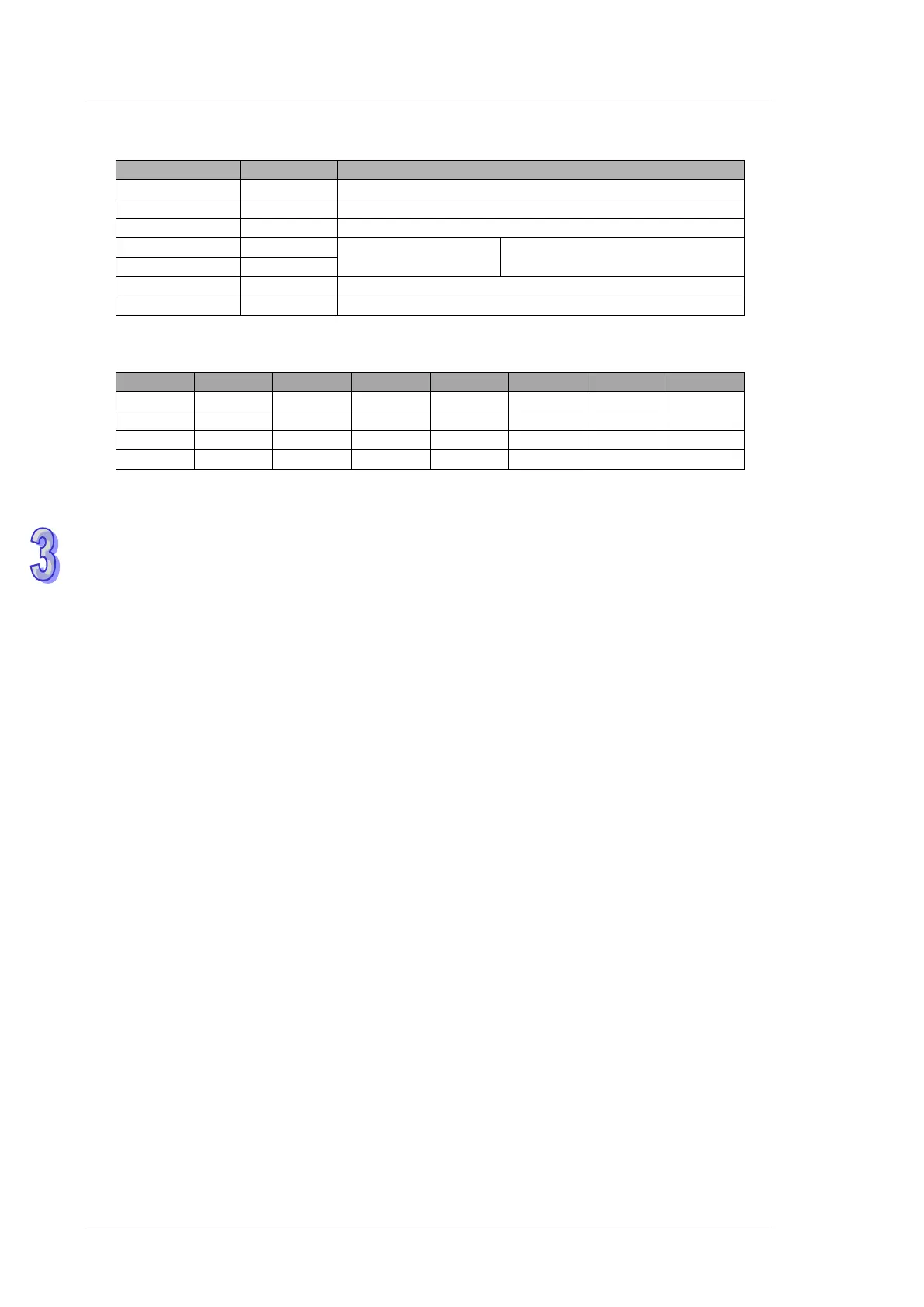
Content of address
H0500~H0515
Analysis of the read status of PLC2 Y0~Y17: 1234H
Program Example 2: COM1(RS-232) / COM3(RS-485), Function Code H02 (H01 is used the
same as H02.)
1. Function code K2 (H02): read multiple bit devices. Up to 64 bits can be read.
2. PLC1 connects to PLC2: (M1320 = OFF, ASCII mode), (M1320 = ON, RTU mode)
3. For both ASCII and RTU modes, PLC COM1/COM3 only stores the received data in registers
starting from S, and will not store the data to be sent. The stored data can be transformed and
moved by using DTM instruction for applications of other purposes.
4. Take the connection between PLC1 (PLC COM3) and PLC2(PLC COM1) for example, the
tables below explains the status when PLC1 reads Y0~Y17 of PLC2
If PLC1 applies COM1 for communication, the below program can be usable by changing:
a) D1109→D1036: communication protocol
b) M1136→M1138: retain communication setting
c) D1252→D1249: Set value for data receiving timeout
d) M1320→M1139: ASCII/RTU mode selection
e) M1316→M1312: sending request
f) M1318→M1314: receiving completed flag