3. Instruction Set
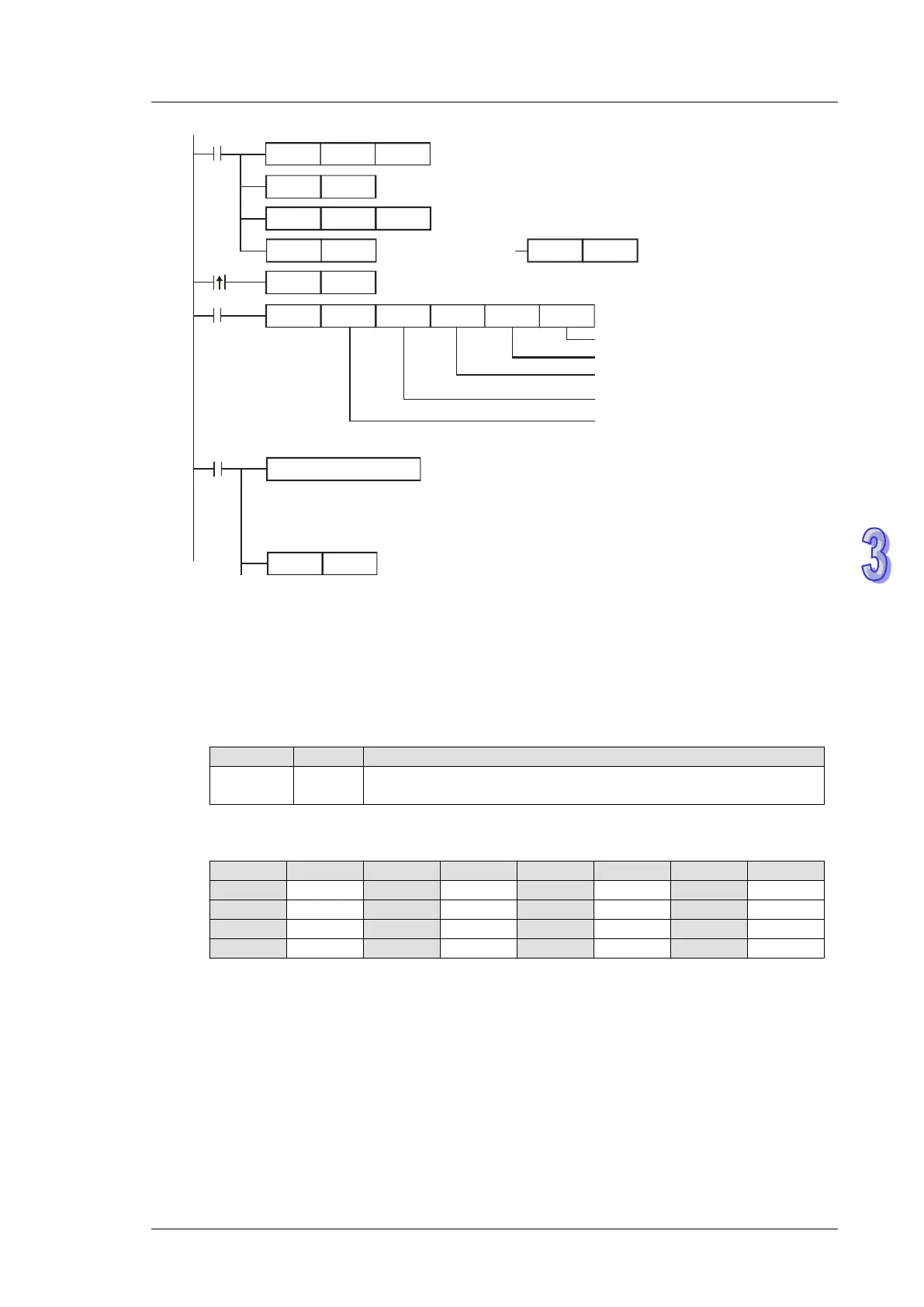
H87
MOV
M1002
D1109
SET
M1136
K100
MOV
D1252
MODRW
K2
K1
X0
H0500 D0 K16
Connection device
address:
K1
Function code: K2
re a d mu ltiple bits
Data address: Y0=H0500
Da ta s torin g re gis te r
Da ta le ngth
(bit)
SET
X0
M1316
M1320 = OFF,
ASCII mode
RST
M1320
SET
M1320
Set communication protocol as 9600,8,E,1
Re ta in communica tion s e ttin g
S e t re ceiving time out a s 100ms
Sending request
M1320 = ON
RTU mode
RST
M1318
Processing received data
Reset M1318
M1318
R e ce iving c o mp le te d
ASCII mode: The receive d data is conve rted to Hex va lue
a nd stored in registers s ta rting from D0
R TU m o de : Th e r e ce ive d d a ta is sto re d in r e g is te rs sta rting fro m D0
ASCII mode (COM3: M1320 = OFF, COM1: M1139 = OFF):
When X0 = ON, MODRW instruction executes the function specified by Function Code 02
PLC1 PLC2, PLC1 sends: “01 02 0500 0010 E8”
PLC2 PLC1, PLC1 receives: “01 02 02 3412 B5”
PLC1 data receiving register D0
D0 1234H
PLC converts the ASCII data in address 0500H~0515H and
stores the converted data automatically.
Analysis of the read status of PLC2 Y0~Y17: 1234H