Chapter 12 Description of Parameter Settings|CFP2000 Series
12.1-02-17
make the drive runs from the low speed to stop.
1.0msec
TRG
[00-04=01]
02-14=17
02-19=5
02-20=3
[02-06=23]
Display value
Counter Trigger
(output signal)
Preliminary Counter Value
RY1 Pr.0 2- 13 =17
Terminal Counter Value
RY2 P r.0 2- 14 =18
The width of trigger signal
02-13, 02-14, 02-36, 02-37
1.0msec
Reserved
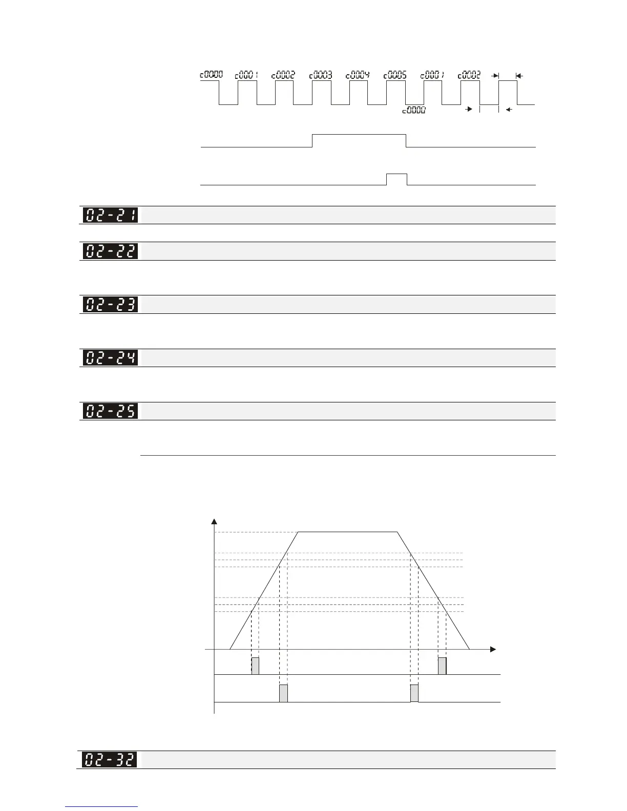
Desired Frequency Attained 1
Factory Setting: 60.00/50.00
Settings 0.00~599.00Hz
The Width of the Desired Frequency Attained 1
Factory Setting: 2.00
Settings 0.00~599.00Hz
Desired Frequency Attained 2
Factory Setting: 60.00/50.00
Settings 0.00~599.00Hz
The Width of the Desired Frequency Attained 2
Factory Setting: 2.00
Settings 0.00~599.00Hz
Once output frequency reaches desired frequency and the corresponding multi-function output
terminal is set to 3 or 4 (Pr.02-13, 02-14, 02-36, and 02-37), this multi-function output terminal will
be ON.
02-13,02-14,
02-36,02-37,
Fcmd=60Hz
02-22=10Hz
02-23=2Hz
02-24=40Hz
02-25=2Hz