Chapter 12 Description of Parameter Settings|CFP2000 Series
12.1-06-21
Level 2 06-57=
Setting range 0.000 10.000V
Factory setting: 7.000V
: ~
Level 1 06-56=
Setting range: 0.000 10.000V
Factory setting: 5.000V
~
Frequency
Command
When voltage of PT100 reaches level 1,
the frequency command goes back to Pr.06-58.
the drive passed the delay time set at Pr06-59 ,
When voltage of PT100 reaches level 2, the drive activate
protecting action by following the setting of Pr.06-29.
Delay time
Pr.06 59-
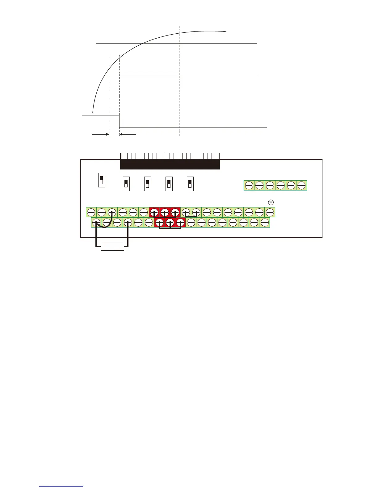
(7) PT100 wiring diagram:
MI1+24V COM FWDMO1 MI5MI3ACI+10V AVIA FM1 MO2
MC M
MI7
MI4DC M RE V MI 2 MI 8MI6ACM-10V A U IAFM2
DFM
SG-SG+
R A 2RC2 RB2 RB1RC1 RA1
0-1 0V
-10-10V
0-10V 0-10V
0-10V
0-20mA
0-2 0m A
0 -20 mA Op en
120
AFM 1
AFM2
AVI
ACI 485
SGNDSTO1 STO 2
SCM1SC M2 D C M
+24V
PT100
Figure 1
When Pr.06-58=0.00Hz, PT100 function is disabled.
Example:
A PT100 is installed to the drive. If motor temperature reaches 135℃ (275°F) or higher, the drive
will decrease motor frequency to the setting of Pr.06-58. Motor will operate at this frequency
(Pr.06-58) till the motor temperature decreases to 135℃(275°F) or lower. If motor temperature
exceeds 150℃(302°F), the motor will decelerate to stop and outputs an ‘OH3’ warning.
Set up process:
1. Switch AFM2 (SW2) to 0-20mA on the I/O control terminal block. (Refer to Figure 1, PT100
wiring diagram)
2. Wiring (Refer to Figure 1, PT100 wiring diagram):
Connect external terminal AFM2 to (+)
Connect external terminal ACM to (-)
Connect external terminals AFM2 and AVI to short-circuit
3. Set Pr.03-00=11 or Pr.03-23=23 or Pr.03-33=45%(9mA)
4. Refer to RTD temperature and resistance comparison table
Temperature=135 , ℃ resistance=151.71Ω; Input current: 9mA, Voltage: approximately:
1.37Vdc
Temperature=150 , ℃ resistance=157.33Ω; Input current:9mA, Voltage: approximately: 1.42Vdc
5. Set Pr.06=56=1.37 and Pr.06-58=10Hz. When RTD temperature increases to 135 or higher, ℃
the drive will decelerate to the selected frequency. When Pr.06-58=0, the drive will not run.
 Loading...
