Chapter 12 Description of Parameter Settings|CFP2000 Series
12.1-12-5
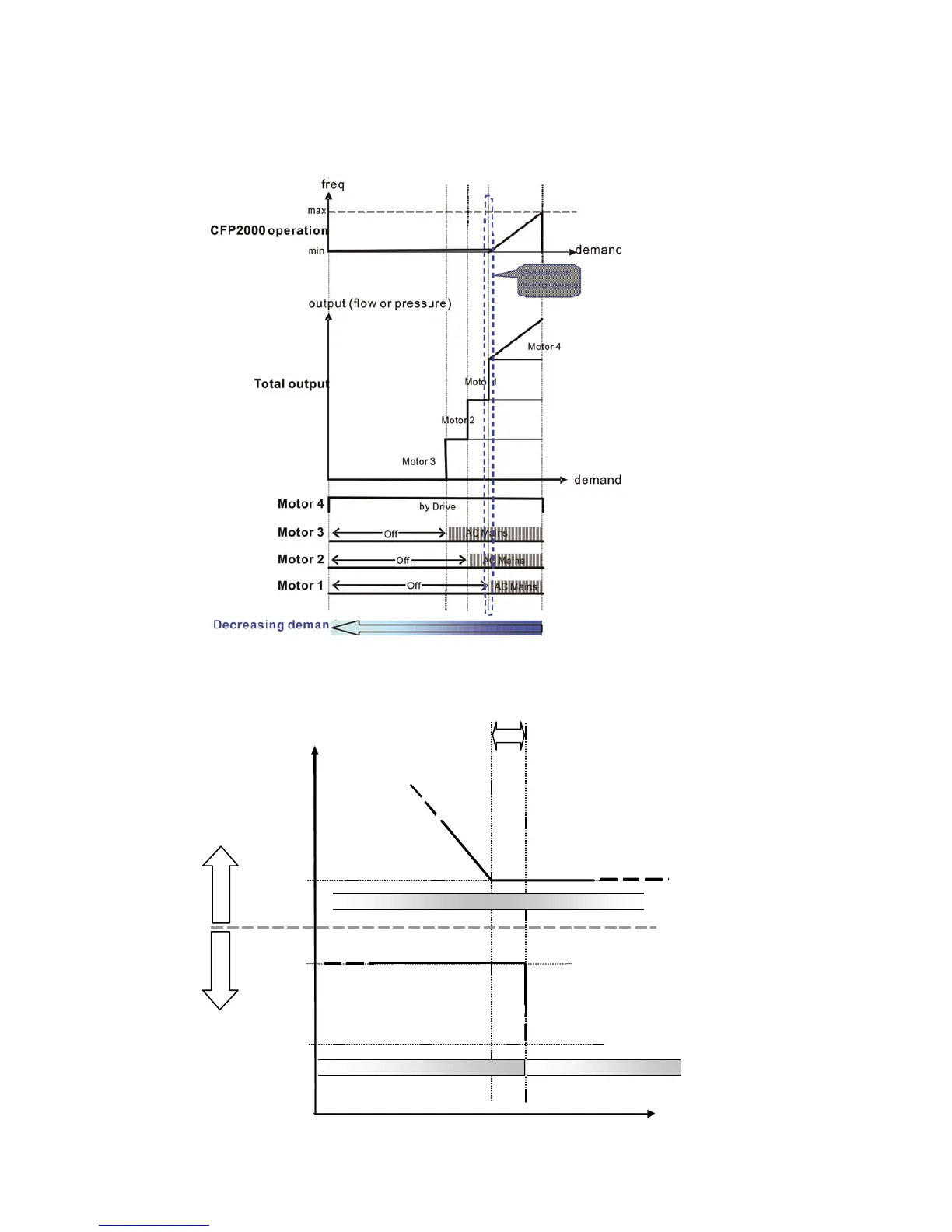
However if decreasing demands when flow quantity and pressure are too big, CFP2000 will
stop the current operating motors and wait for the delay time setting of Pr12-04. Then keep on
doing this until the last motor stop using mains electricity. See sequential diagram 12-5 and
12-6 below.
Diagram 12-5: Sequence of switching motors at fixed quantity circulation with PID – Decreasing
Demands
mains (50Hz)
Td
Motor #4 by Drive
Motor #4
Motor #1
Motor #1 off (coasting)
Motor #1 on mains
0H
time
freq
0Hz
Td = (P12-04 x 2) + 2 sec
Diagram 12-6: Sequence of switching motors at fixed quantity circulation with PID – Decreasing
Demands