129
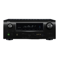
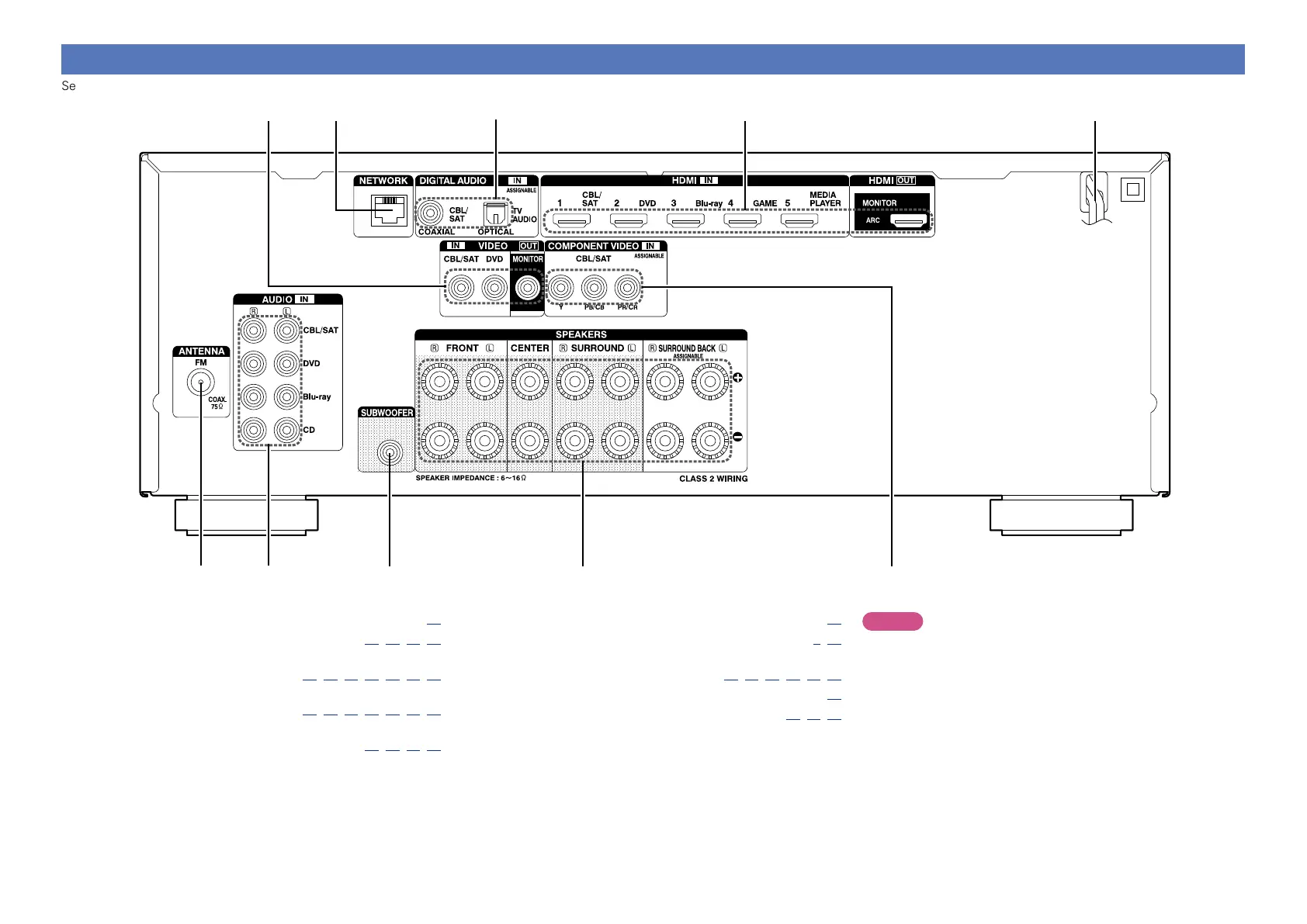
Rear panel
See the page indicated in parentheses ( ).
q w e r t
u
yo iQ0
q FM antenna terminal (ANTENNA) ········································· (20)
w Analog audio connectors (AUDIO) ······················ (16, 15, 14, 19)
e Subwoofer connector
(SUBWOOFER) ····································· (77, 78, 79, 80, 81, 82, 83)
r Speaker terminals
(SPEAKERS) ········································· (77, 78, 79, 80, 81, 82, 83)
t Component video connectors
(COMPONENT VIDEO) ·········································· (16, 15, 14, 17)
y Power cord ··············································································· (22)
u HDMI connectors ································································· (9, 10)
i Digital audio connectors
(DIGITAL AUDIO) ······································· (13, 16, 15, 14, 17, 19)
o Network connector (NETWORK) ··········································· (21)
Q0 Video connectors (VIDEO) ·········································· (13, 15, 14)
NOTE
Do not touch the inner pins of the connectors on the rear panel.
Electrostatic discharge may cause permanent damage to the unit.
 Loading...