Do you have a question about the Denon DN-S3500 and is the answer not in the manual?
Specifies target regions and models for the service manual.
Covers general safety, design changes, manual usage, and illustration differences.
Procedures for leakage current, line-to-chassis resistance, and laser safety.
Highlights important service points, electrical shock risks, and using specified parts.
Steps to remove the bottom plate, including screw removal.
Procedure for removing the top cover, FFC cable, and connectors.
Instructions for removing the motor unit by unscrewing.
Procedure for detaching the mecha unit, involving screw and FFC removal.
Steps to remove the Power P.W.B. by unscrewing.
Procedure for short-circuiting, removing screws, and detaching the Main P.W.B.
Instructions for removing the shield plate for specific models.
Steps to remove the CD Mecha and Disc Guide by unscrewing.
Illustrates the functional blocks and interconnections of the system.
Explanation of the service program for confirming servo functions.
Lists necessary measuring tools, specifically reference discs.
Details how to enter and navigate the service mode.
Table showing adjustment values and OK ranges for servo parameters.
Describes various test modes like Heat Run, Chucking Test, and System Check.
Lists error codes that appear during specific test functions.
Procedure for updating the system µcom and DSP via disc.
Instructions for adjusting platter rotation speed after motor replacement.
Details of integrated circuits, focusing on MN102H730F (IC101).
Detailed pin assignments and functions for various ICs.
Continued pin assignments and functions for various ICs.
Pin assignments and functions for the ADSP-BF531 IC.
Detailed pin assignments and functions for various ICs.
Detailed pin assignments and functions for various ICs.
Detailed pin assignments and functions for various ICs.
Pin assignments and functions for the MN6627933 IC.
Detailed pin assignments and functions for various ICs.
Detailed pin assignments and functions for various ICs.
Schematic diagram for AN8785SB IC.
Schematic diagram for AN22002A IC.
Block diagram and pinout for PCM1748 IC.
Circuit diagram and pinout for GP1A038RBK IC.
Pin assignments and descriptions for SDRAM ICs.
Block diagram and pinout for BU2090F IC.
Pinout for TPC6103 IC.
Pinout for TOP247YN IC.
Block diagram and pinout for NJM2626 IC.
Circuit diagram and pinout for EW-510 IC.
Pin connection details and notes for the FL Display.
Component layout for the GU-3689 Main Printed Wiring Board.
Component layout on the foil side of the Main Printed Wiring Board.
Component layout for the GU-3690 Power Printed Wiring Board.
Component layout on the foil side of the Power Printed Wiring Board.
Component layout for the GU-3691 Panel Printed Wiring Board.
Component layout on the foil side of the Panel Printed Wiring Board.
Component layout for the GU-3717 Panel Printed Wiring Board.
Explains symbols like 'nsp', '*', and warnings for parts list entries.
Provides details on resistor types, performance, and notation.
Explains capacitor types, performance, and notation for values.
List of semiconductor components used on the P.W.B. unit.
List of capacitor components used on the P.W.B. unit.
Continuation of capacitor components list with part numbers.
More capacitor components listed with part numbers and remarks.
List of other miscellaneous parts like connectors and FFCs.
Lists additional miscellaneous components like oscillators and radiators.
List of IC components with part numbers and remarks.
List of transistors, diodes, and resistors with part numbers and remarks.
List of capacitor components with part numbers and remarks.
More capacitor components listed with part numbers and remarks.
List of other parts like connectors, fuses, and switches.
List of ICs with part numbers and remarks, including BU2090F.
List of transistors, diodes, LEDs, and FL display with part numbers.
List of resistors, including slide volume, and capacitors.
List of connectors, switches, and holders.
List of ICs, diodes, capacitors, and connectors with part numbers.
Visual breakdown of the main unit's components and their assembly.
Detailed list of parts for the main unit, including WEEE mark and material.
List of screws used in the assembly, with specifications.
Continuation of the screws list with part numbers and material.
Lists items included in the packing and accessories, with WEEE mark info.
Shows wiring connections between different units of the main system.
Explains symbols, units, and warnings for schematic diagrams.
Detailed circuit diagrams for the Main unit (Part 1).
Detailed circuit diagrams for the Main unit (Part 2).
Circuit diagrams for Motor and Power units.
Circuit diagrams for various panel and interface units.
List of main unit parts marked for recycling, including material and WEEE mark.
List of screws with part numbers, material, and quantity.
Continuation of the screws list with part numbers and material.
Visual breakdown of the main unit's components and their assembly.
List of DD Motor unit parts, including WEEE mark and material.
List of screws for the DD Motor unit with part numbers and material.
Visual breakdown of the DD Motor unit components and their assembly.
List of CD Mechanism unit parts, including WEEE mark and material.
Continuation of CD Mechanism unit parts list.
More parts listed for the CD Mechanism unit.
Visual breakdown of the CD Mechanism unit components and their assembly.
| Frequency Response | 20 Hz - 20 kHz |
|---|---|
| Jog Wheel | Yes |
| Fader Start | Yes |
| Power Supply | AC 120V, 60Hz |
| Playback Formats | CD, MP3 |
| Digital Outputs | Coaxial |
| Analog Outputs | RCA |
| Dimensions | 320 x 260 x 100 mm |
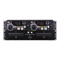
| Type | CD/MP3 Player |