90
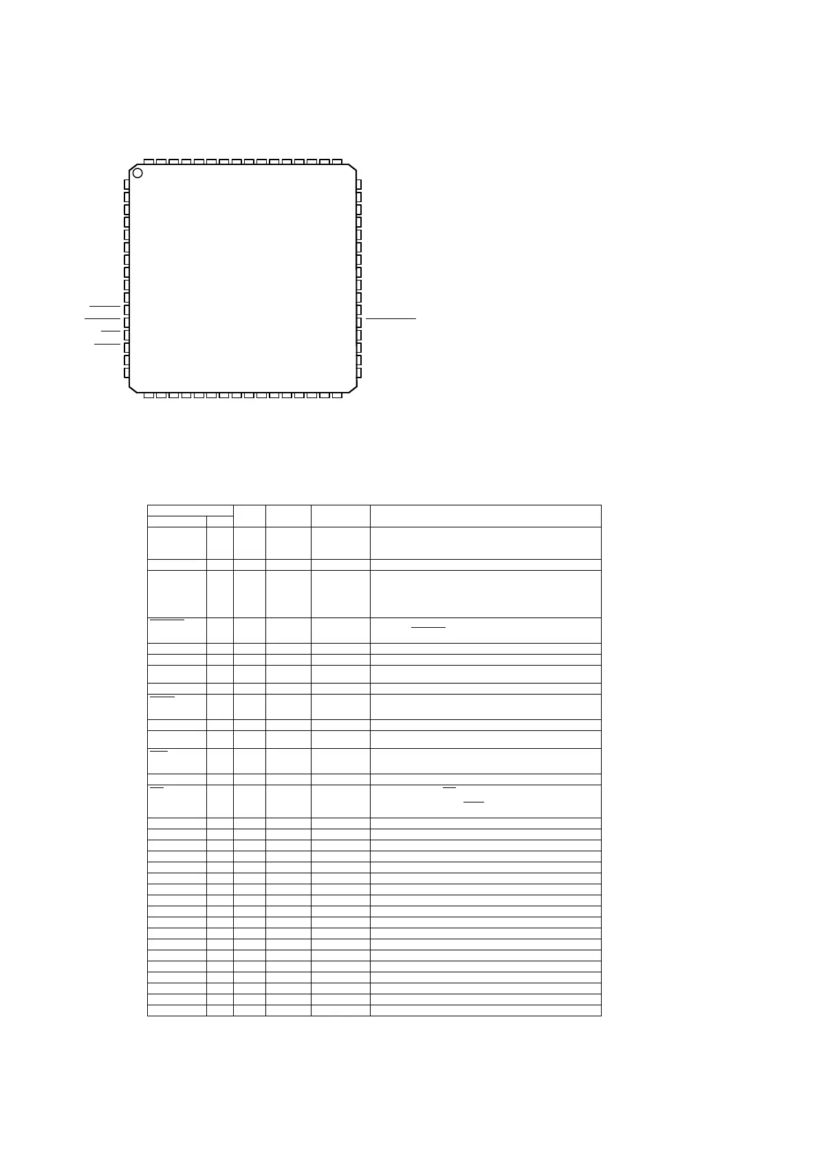
TAS5508C(MAIN:IC108)
TAS5508PinDiscriptions
2 Description
2.1 Physical Characteristics
2.1.1 Terminal Assignments
17
VR_PWM
PWM_P_4
PWM_M_4
PWM_P_3
PWM_M_3
PWM_P_2
PWM_M_2
PWM_P_1
PWM_M_1
VALID
DVSS
BKND_ERR
DVDD
DVSS
DVSS
VR_DIG
48
47
46
45
44
43
42
41
40
39
38
37
36
35
34
33
1
2
3
4
5
6
7
8
9
10
11
12
13
14
15
16
VRA_PLL
PLL_FLT_RET
PLL_FLTM
PLL_FLTP
AVSS
AVSS
VRD_PLL
AVSS_PLL
AVDD_PLL
VBGAP
RESET
HP_SEL
PDN
MUTE
DVDD
DVSS
18 19 20 21 22 23 24 25 26 27 28 29 30 31 32
64 63 62 61 60 59 58 57 56 55 54 53 52 51 50 49
VR_DPLL
OSC_CAP
XTL_OUT
XTL_IN
RESERVED
RESERVED
RESERVED
SDA
SCL
LRCLK
SCLK
SDIN4
SDIN3
SDIN2
SDIN1
PSVC
RESEVED
MCLK
PWM_HPPR
PWM_HPMR
PWM_HPPL
PWM_HPML
PWM_P_6
PWM_M_6
PWM_P_5
PWM_M_5
DVDD_PWM
DVSS_PWM
PWM_P_8
PWM_M_8
PWM_P_7
PWM_M_7
2.1.2 Ordering Information
TAS5508
8-Channel Digital Audio PWM Processor
SLES091C–FEBRUARY 2004–REVISED AUGUST 2005
T
A
PLASTIC 64-PIN PQFP (PN)
0°C to 70°C TAS5508PAG
Description 17
2.1.3 Terminal Descriptions
TAS5508
8-Channel Digital Audio PWM Processor
SLES091C–FEBRUARY 2004–REVISED AUGUST 2005
TERMINAL
5-V
TYPE
(1)
TERMINATION
(2)
DESCRIPTION
TOLERANT
NAME NO.
AVDD_PLL 9 P 3.3-V analog power supply for PLL. This terminal can be connected to the same
power source used to drive power terminal DVDD, but to achieve low PLL jitter,
this terminal should be bypassed to AVSS_PLL with a 0.1-µF low-ESR
capacitor.
AVSS 5, 6 P Analog ground
AVSS_PLL 8 P Analog ground for PLL. This terminal should reference the same ground as
terminal DVSS, but to achieve low PLL jitter, ground noise at this terminal must
be minimized. The availability of the AVSS terminal allows a designer to use
optimizing techniques such as star ground connections, separate ground planes,
or other quiet ground-distribution techniques to achieve a quiet ground reference
at this terminal.
BKND_ERR
37 DI Pullup Active-low. A back-end error sequence is generated by applying logic low to this
terminal. The BKND_ERR results in no change to any system parameters, with
all H-bridge drive signals going to a hard-mute (M) state.
DVDD 15, 36 P 3.3-V digital power supply
DVDD_PWM 54 P 3.3-V digital power supply for PWM
DVSS 16, 34, P Digital ground
35, 38
DVSS_PWM 53 P Digital ground for PWM
HP_SEL
12 DI 5 V Pullup Headphone in/out selector. When a logic low is applied, the headphone is
selected (speakers are off). When a logic high is applied, speakers are selected
(headphone is off).
LRCLK 26 DI 5 V Serial-audio data left/right clock (sampling-rate clock)
MCLK 63 DI 5 V Pulldown MCLK is a 3.3-V master clock input. The input frequency of this clock can range
from 4 MHz to 50 MHz.
MUTE
14 DI 5 V Pullup Soft mute of outputs, active-low (muted signal = a logic low, normal operation =
a logic high). The mute control provides a noiseless volume ramp to silence.
Releasing mute provides a noiseless ramp to previous volume.
OSC_CAP 18 AO Oscillator capacitor
PDN
13 DI 5 V Pullup Power down, active-low. PDN powers down all logic and stops all clocks
whenever a logic low is applied. The internal parameters are preserved through
a power-down cycle, as long as RESET is not active. The duration for system
recovery from power down is 100 ms.
PLL_FLT_RET 2 AO PLL external filter return
PLL_FLTM 3 AO PLL negative input. Connected to PLL_FLT_RTN via an RC network
PLL_FLTP 4 AI PLL positive input. Connected to PLL_FLT_RTN via an RC network
PSVC 32 O Power-supply volume control PWM output
PWM_HPML 59 DO PWM left-channel headphone (differential –)
PWM_HPMR 61 DO PWM right-channel headphone (differential –)
PWM_HPPL 60 DO PWM left-channel headphone (differential +)
PWM_HPPR 62 DO PWM right-channel headphone (differential +)
PWM_M_1 40 DO PWM 1 output (differential –)
PWM_M_2 42 DO PWM 2 output (differential –)
PWM_M_3 44 DO PWM 3 output (differential –)
PWM_M_4 46 DO PWM 4 output (differential –)
PWM_M_5 55 DO PWM 5 output (differential –)
PWM_M_6 57 DO PWM 6 output (differential –)
PWM_M_7 49 DO PWM 7 (lineout L) output (differential –)
PWM_M_8 51 DO PWM 8 (lineout R) output (differential –)
PWM_P_1 41 DO PWM 1 output (differential +)
PWM_P_2 43 DO PWM 2 output (differential +)
(1) Type: A = analog; D = 3.3-V digital; P = power/ground/decoupling; I = input; O = output
(2) All pullups are 200-mA weak pullups and all pulldowns are 200-mA weak pulldowns. The pullups and pulldowns are included to ensure
proper input logic levels if the terminals are left unconnected (pullups => logic-1 input; pulldowns => logic-0 input). Devices that drive
inputs with pullups must be able to sink 200 mA, while maintaining a logic-0 drive level. Devices that drive inputs with pulldowns must be
able to source 200 mA, while maintaining a logic-1 drive level.
 Loading...