SECTION 6 - SCREEN RETENTION SYSTEM
15 Jun 12 6-1
HyperPoolShaker
GENERAL
Proper screen functioning depends on tightness and full contact with the screen bed components,
(side supports, cross supports, and bulkhead protectors). The screen compression assembly is
designed to properly secure the screen panels for optimum performance and durability.
The HyperPool shaker is identified as either right- or left-hand, which designates the screen
compression side of the machine. This arrangement allows an operator to work from one side of
the machine to install and remove screen panels.
DESCRIPTION
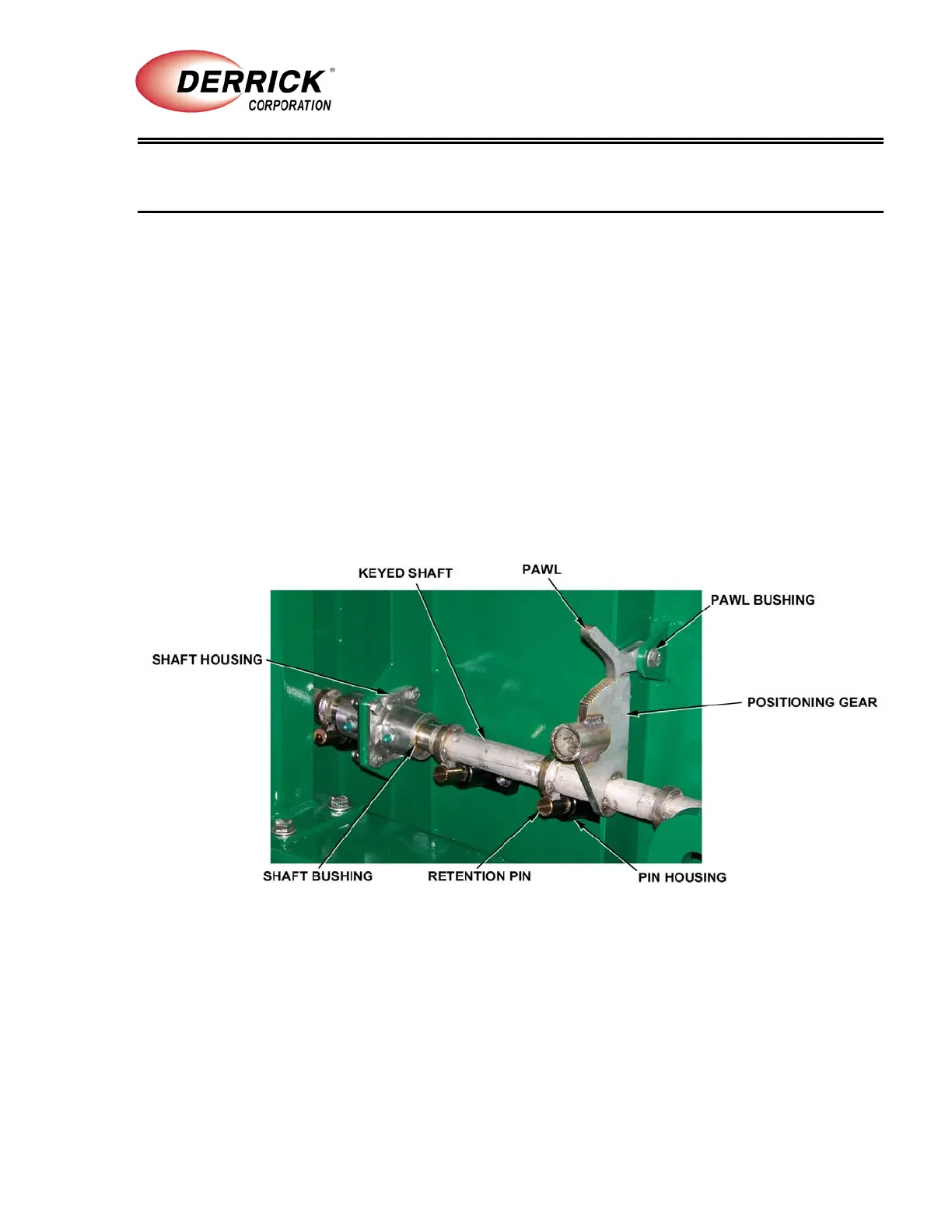
The screen compression system (Figure 6-1) consists of four manually operated compression
assemblies that extend retention pins outward to press against the edges of the screen panel.
When fully extended, the pins cause the screen to curve downward into intimate contact with the
screen bed. In this way, the bowed screen is tightly retained against the bed components, forming
a complete seal.
Figure 6-1. Screen Compression System