6159924330 - 08/2020 - 43 -
TRA and D53 positioning arms
Check that the eBUS cable is connected from the encoder M12 or T-junction in case of 2 encoders.
Connect an ePOD2 or above to the controller.
Ensure you have a tape meter and a protractor close at hand to measure the characteristics of your installation.
To get more information, refer to the user manuals of the positioning arms at https://www.desouttertools.com/
resource-centre.
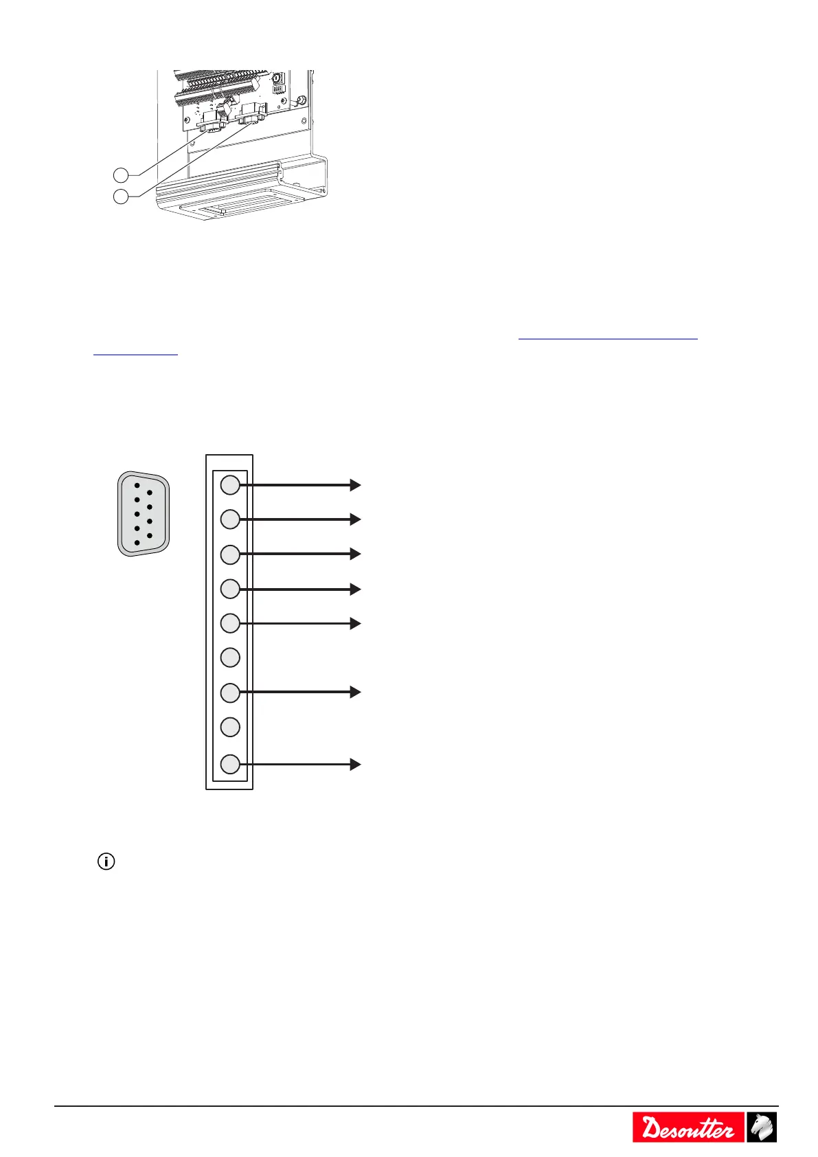
Connecting eBUS cable to the controller
Connect the eBUS cable to the bottom panel of the controller.
eBUS connector wiring diagram
B -
GND-EXT
AGND
2
3
B +
5
6
7
8
+24V-EXT
+24V
0V
9
1
4
9
8
7
6
5
4
3
2
1
Installing an ePOD
Always use the "Eject" command of the controller before removing the ePOD.
 Loading...