13
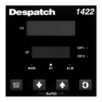
FIGURE 2-7A
24V Nominal AC/DC Supply
The supply connection for the 24V AC/DC option of the instrument are as shown below.
Power should be connected via a two pole isolating switch and a 315 mA slow-blow
(anti-surge type T) fuse. With the 24V AC/DC supply option fitted, these terminals will
accept the following supply voltage ranges:
24V (nominal) AC 50/60 Hz - 20 - 50 V
24V (nominal) DC - 22 - 65 V
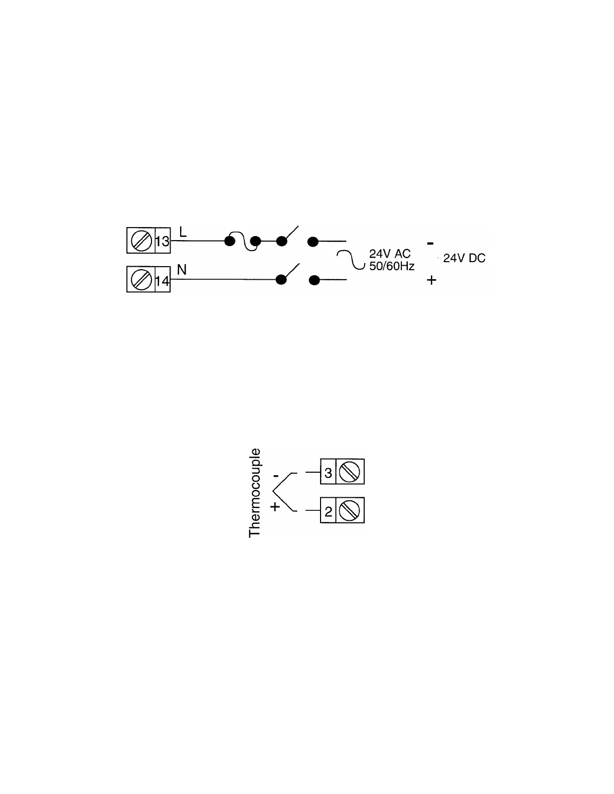
FIGURE 2-8
Thermocouple (T/C) Input
Make thermocouple connections as illustrated below. Connect the positive
leg of the thermocouple to terminal 2 and the negative leg to terminal 3.
Note: Thermocouple must not be grounded! Damage to the cold junction in the
control will result!