14
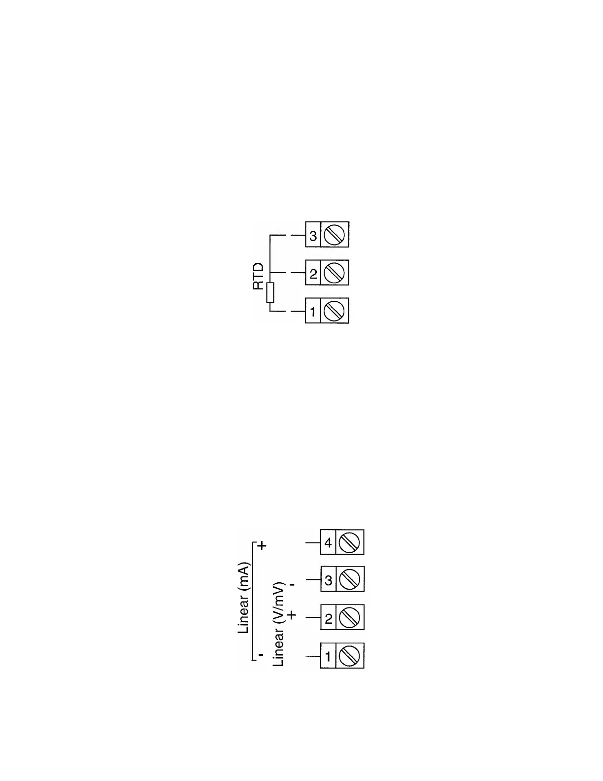
FIGURE 2-9
RTD Input
Make RTD connections as illustrated below. For a three wire RTD, connect the
resistive leg of RTD to terminal 1 and the common legs to terminals 2 and 3. For a two
wire RTD, connect one leg to terminal 2 and the other leg to terminal 3 as shown below.
A jumper wire supplied by the customer must be installed between terminals 2 and 3.
Input conditioning jumper must be positioned correctly (see Appendix B) and Hardware
Definition Code must be correct (see Section 8, Configuration Mode).
FIGURE 2-10
Volt, mV Input
Make volt and millivolt connections as shown below. Terminal 2 is positive and terminal
3 is negative. Input conditioning jumper must be positioned correctly (see Appendix A)
and Hardware Definition Code must be correct (see Section 8, Configuration Mode).
mADC Input
Make mADC connections as shown below. Terminal 4 is positive and terminal 1 is
negative. Input conditioning jumper must be positioned correctly (see Appendix A) and
Hardware Definition Code must be correct (see Section 8, Configuration Mode).