2.2 95-871420
NOTE
To establish the optional “communication
link” between the transmitter and receiver,
connect a three-wire shielded cable to the
INTR A, INTR B, and INTR GND terminals
of the two devices. See Figure 20. Take
care not to connect any of these lines
to 0V COM. Doing so will damage the
4-20 mA circuit and make the device
susceptible to surge.
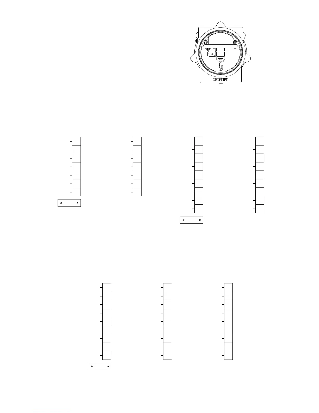
Figure 10—Terminal Strip Located Inside Wiring Compartment
SPARE
RS-485 B
INTR B
SHIELD
SHIELD
0V COM
0V COM
8
7
6
5
4
3
2
INTR GND
RS-485 A
INTR A
SHIELD
SHIELD
+24 VDC
+24 VDC
17
16
15
14
13
12
18
A2646
HART
Figure 11—Transmitter Wiring Terminal Identication
–4-20mA
CAL
RS-485 B
INTR B
SHIELD
SHIELD
0V COM
0V COM
0V COM
1
2
3
4
5
6
7
8
9
+4-20mA
INTR GND
RS-485 A
INTR A
SHIELD
SHIELD
+24 VDC
SPARE
+24 VDC
11
12
13
14
15
16
17
18
19
A2645
HART
Figure 12—Wiring Terminal Identication for LS2000 Receiver
without Relays
mA–
RESET/CAL
RS-485 B
INTR B
SHIELD
SHIELD
0V COM
0V COM
0V COM
1
2
3
4
5
6
7
8
9
mA+
INTR GND
RS-485 A
INTR A
SHIELD
SHIELD
+24 VDC
SPARE
+24 VDC
11
12
13
14
15
16
17
18
19
HI ALARM NO
LO ALARM NO
HI ALARM NC
LO ALARM NC
HI ALARM COM
LO ALARM COM
FAULT NO
FAULT COM
FAULT NC
21
22
23
24
25
26
27
28
29
A2643
HART
Figure 13—Wiring Terminal Identication for LS2000 Receiver with Relays