2.2 95-87142
opERation ovERviEw
THEORY OF OPERATION
The LS2000 transmitter module uses a
Xenon flash lamp to produce a collimated IR
light source. This light source illuminates the
path between transmitter and receiver. The
transmitter uses a filter to block visible light
emissions and is eye safe.
As flammable hydrocarbon gases intersect the
light beam between the two modules, certain
IR wavelengths are absorbed by the gas, while
other IR wavelengths are not. The amount of IR
absorption is determined by the concentration of
the hydrocarbon gas. A pair of optical detectors
and associated electronics located in the
receiver module measure the absorption. The
change in intensity of the absorbed light (active
signal) is measured relative to the intensity of
light at a non-absorbed wavelength (reference
signal). The microprocessor computes the
gas concentration and converts the value
into a 4-20 mA current output signal, which
is then communicated to external control and
annunciation systems.
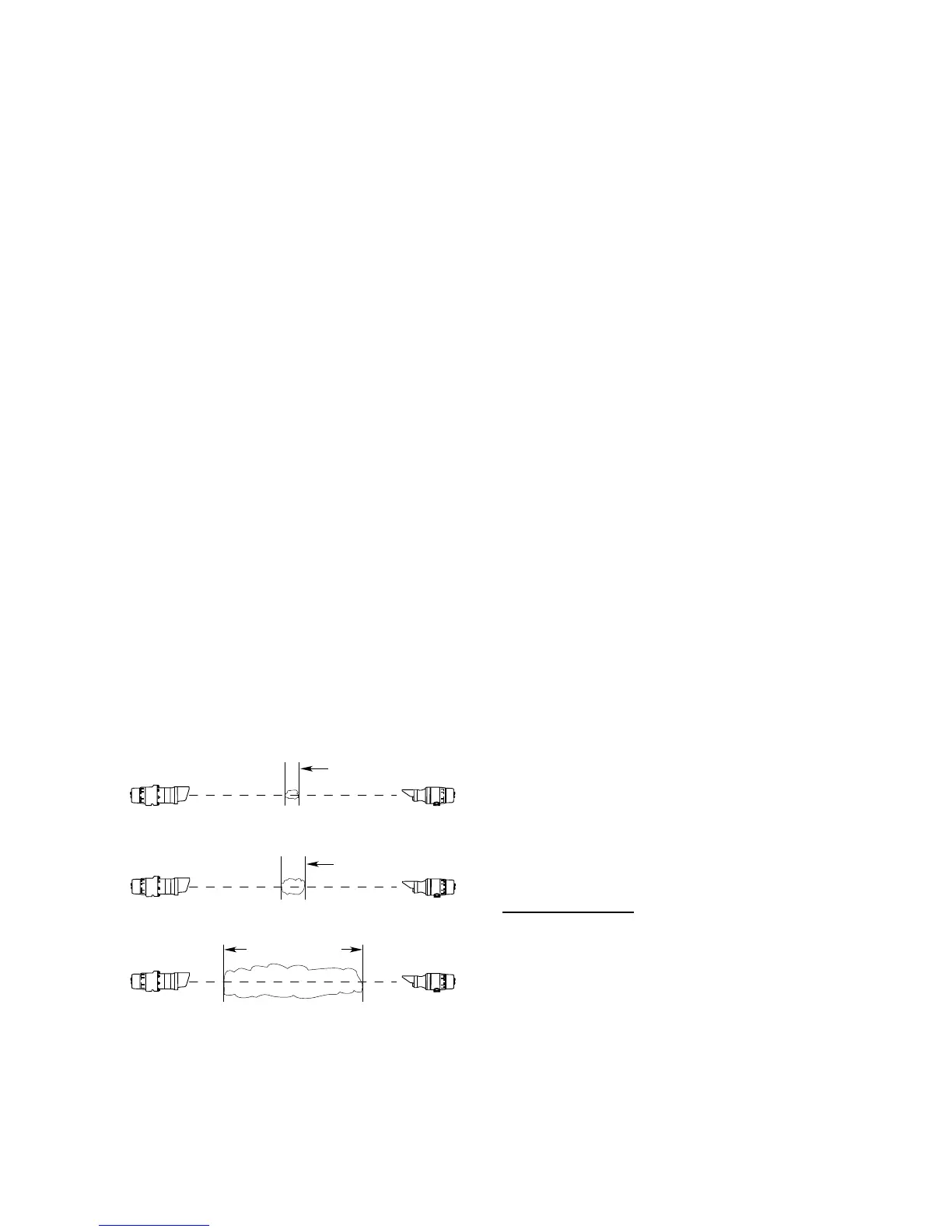
The gas concentration is indicated by a 4-20 mA
signal, which corresponds to 0-5 LFL-meters.
To better understand the concept of LFL-meters,
refer to Figure 1, which shows how three gas
clouds of different size and concentration would
produce the same output of 1 LFL-meter by the
line of sight gas detection system. To convert
a given LFL-m value to ppm-m for methane,
propane or butane gas, refer to Table 1.
DETECTABLE GASES
The LS2000 is capable of detecting most
hydrocarbon gases and vapors including
methane, propane, and butane. Gas type
and other operational parameters are selected
via HART or MODBUS communication. The
LS2000 is factory calibrated to methane,
propane, and butane, and comes from the
factory set for methane.
DETECTION RANGES
The LS2000 is offered in two detection ranges in
order to meet customer needs, as listed below:
Short Range 5-60 meters
Long Range 30-120 meters
For installations with short separation distances
(5-15 meters for the short range model and
30-40 meters for the long range model), the
range reduction aperture kit (supplied) is
required. Refer to “Aperture Kit for Short Range
Applications” section in this manual for details.
The correct range for the LS2000 must be
chosen to meet specific application needs.
The detection range of the LS2000 pair is
determined by the Receiver. Receiver units
can be converted from long to short or short
to long range in the field by replacing the front
electronics module. A single transmitter model
is used for both detection range options.
STANDARD OUTPUT
The
LS2000
receiver module provides an analog
4-20 mA signal output. HART and RS-485
MODBUS serial communication are available
at either module.
The 4-20 mA current loop
corresponding to 0 to 5 LFL-meters is provided
for connection to analog input devices such as
gas controllers, logic controllers, or distributed
control systems (DCS). To convert the mA
reading to LFL-meters, use the following formula:
mA Reading –4
X 5 = LFL-Meters
16
1M @ 100% LFL = 1 LFL-M
2M @ 50% LFL = 1 LFL-M
10M @ 10% LFL = 1 LFL-M