23 95-87142.2
aliGnmEnt
OVERVIEW
The LS2000 modules must be properly aligned
before normal operation will be attained.
NOTE
Refer to the FM, ATEX, or IECEx Appendix
for information regarding the effect of
misalignment on system accuracy.
IMPORTANT
Upon completion of system alignment,
ensure that ALL bolts on the LS2000
mounting and alignment bracket are
properly tightened.
EQUIPMENT REQUIRED
1. Properly installed and powered LS2000
system (transmitter and receiver). Easy
access to both modules is highly
recommended.
2.
LS2000 Alignment Tool. The alignment tool
is recommended for use in commissioning all
LS2000 systems. The following instructions
cover the use of the Alignment Tool.
3. 9/16 inch wrench.
4. 15/16 inch wrench.
5. For installations with short separation
distances (5-15 meters for the short range
model and 30-40 meters for the long range
model), the short range aperture kit (supplied)
is typically needed. Refer to “Aperture Kit
for Short Range Applications” section in this
manual for details.
ALIGNMENT PROCEDURE
1. Ensure that the system modules are located
within the specified separation range and
securely fixed to the support structures.
Bypass all external gas alarm devices that are
connected to the receiver outputs.
2. Ensure that the system modules are installed
with their windows at approximately the same
height above grade. Each module should be
roughly aligned to face in the direction of the
other module.
3. Loosen the Horizontal and Vertical
Adjustment Bolts on the mounting and
alignment bracket using the 9/16” wrench
for the Horizontal Adjustment Bolts and the
15/16” wrench for the Vertical Adjustment
Bolts. See Figure 21.
4. Loosen the four Horizontal Locking Bolts on
top of the mounting and alignment bracket
using a 9/16” wrench, then retighten until just
snug against the top plate of the Detector
Mounting Assembly. The Detector Mounting
Assembly should still be able to rotate on
its axis when adjusting the Horizontal
Adjustment Bolts. If not, slightly loosen the
four Horizontal Locking bolts.
5. Remove the brow by gently working side to
side while pulling forward.
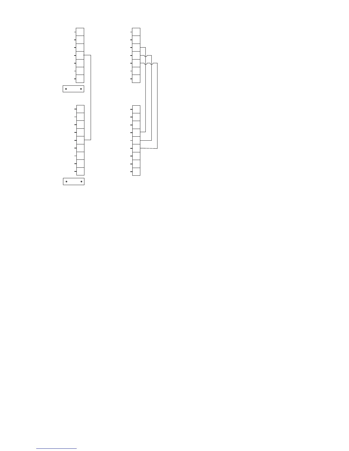
A2667
+4-20mA
INTR GND
RS-485 A
INTR A
SHIELD
SHIELD
+24 VDC
SPARE
+24 VDC
11
12
13
14
15
16
17
18
19
–4-20mA
CAL
RS-485 B
INTR B
SHIELD
SHIELD
0V COM
0V COM
0V COM
1
2
3
4
5
6
7
8
9
HART
CAUTION: DO NOT CONNECT THE COMMUNICATION LINK “INTR GND”
TERMINAL TO POWER SUPPLY COMMON OR ANY OTHER