5 95-87142.2
opERation
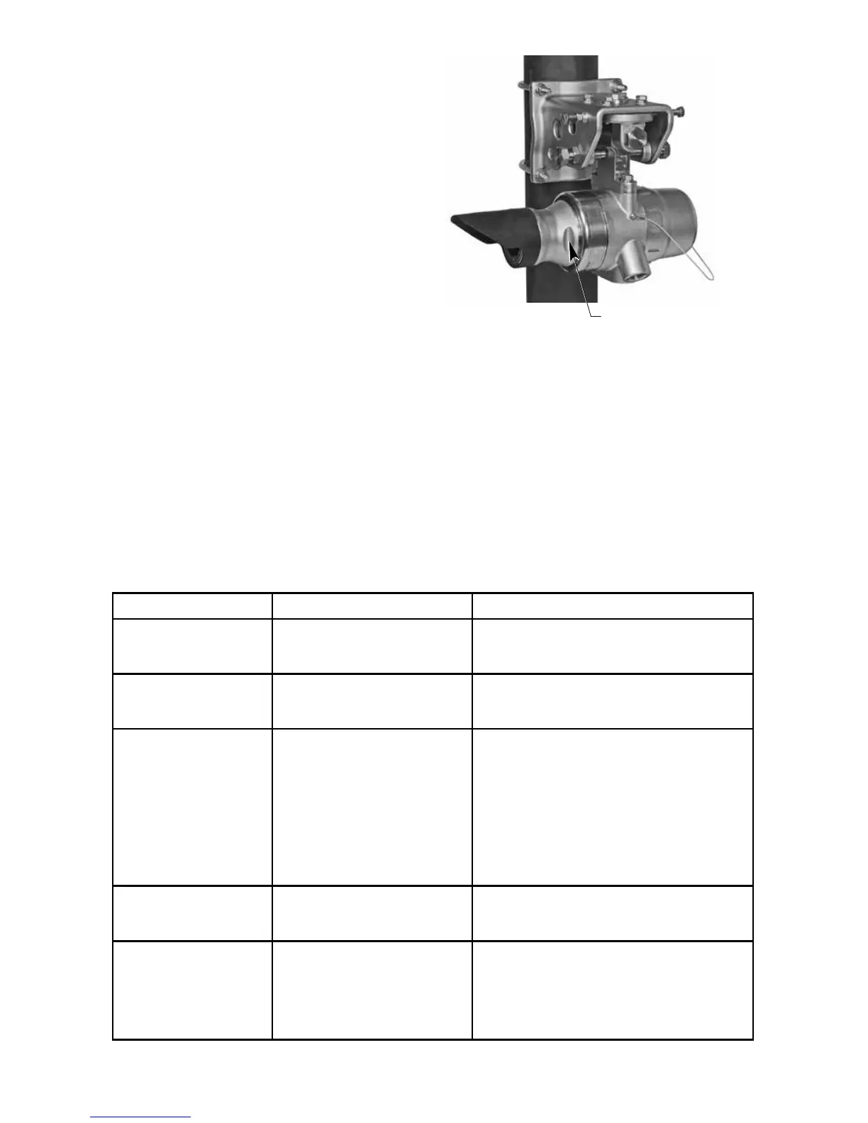
INTERNAL MAGNETIC SWITCH /
CALIBRATION LINE TERMINAL
An internal magnetic switch is provided for
resetting latched alarms and initiating field zero
calibration. See Figure 2 for switch location.
The same functions can be accomplished
remotely by installing a switch (momentary
closure) between the CAL and 0V COM
terminals on the LS2000 receiver. Momentary
switch activation will reset alarms, while holding
the switch closed for 3 seconds or longer (not
to exceed 30 seconds) will start the calibration
sequence. The LEDs will begin flashing green
(5 Hz) when the reset criteria have been met and
will change to flashing yellow (5 Hz) when the
calibration period has been met (>3 seconds,
<30 seconds). The device will reset if the switch
is released during a flashing green LED and will
enter calibration if the switch is released during a
flashing yellow LED.
MODULE IDENTIFICATION
See Figure 3 for identification of the transmitter
and receiver modules. The functional and
electrical characteristic differences of the two
devices are described in Table 2.
FACTORY RESET COMMAND
The LS2000 provides a factory reset command
that sets all user configurable parameters
back to their default settings. This command
can be accessed via HART or MODBUS
communication.
PLACE CALIBRATION MAGNET HERE
TO ACTIVATE INTERNAL REED SWITCH
A2648
Figure 2—Location of Internal Magnetic Switch
on Receiver Module
Table 2—Functional and Electrical Comparison of Transmitter and Receiver
Characteristic Transmitter Receiver
Functional Description Contains a xenon flash lamp,
and generates optical energy to
enable hydrocarbon detection.
Contains opto-electronics, signal processing,
output drivers, and diagnostic electronics.
Electrical Connections Connections for power, HART,
RS-485, Communication Link.
Connections for power, 4-20 mA, HART,
RS-485, relay contacts (optional),
Communication Link, and calibration/reset.
Onboard LED Indicators Indicates device status.
Green indicates normal
operation.
Yellow indicates fault condition.
When the Communication Link
is used, the transmitter LED
operation matches receiver
LED operation, including alarm
status.
Indicates normal, alarm, fault, and calibration
status.
Green indicates normal operation. Blinking red
indicates low gas alarm condition.
Steady red indicates high gas alarm condition.
Yellow indicates system fault. See Tables 4 and
5 for details.
LED operation for fault status is non-latching.
LED operation for gas alarms is configurable
for latching/non-latching.
Magnetic Calibration
Switch (See Figure 2 for
switch location.)
NA Momentary activation provides reset function
for latched alarm outputs. Activation for longer
than 3 seconds will initiate zero calibration.
Adjustable Settings Programmable IR signal intensity
and heater operation. HART
or MODBUS communication is
required to change the factory
default settings.
Factory calibrated for methane, propane, and
butane, 0-5 LFL-meters full scale. Default gas
depends on model. See Table 3 for receiver
factory default settings. HART or MODBUS
communication is required to change the
factory default settings.