7 95-87142.2
HEATER CONTROL
The LS2000 optics in both transmitter and
receiver are heated to provide moisture and ice
resistance. These heaters are microprocessor
controlled and can be configured to operate in
the following modes:
– Always On
– Always Off
– Smart Mode (default)
1) Heaters maintain a user programmable
temperature set point (default = 50°C).
2) Heaters increase to full power when signal
strength is degraded due to moisture or
condensation on the window, or any
obscuration faults are active.
3) Heaters shut off when the input voltage
drops below a user defined level (default =
18.5 Vdc).
4) Heater power usage can be limited from
0-100% (default uses up to 100% power
if needed). See Specifications section for
power consumption details.
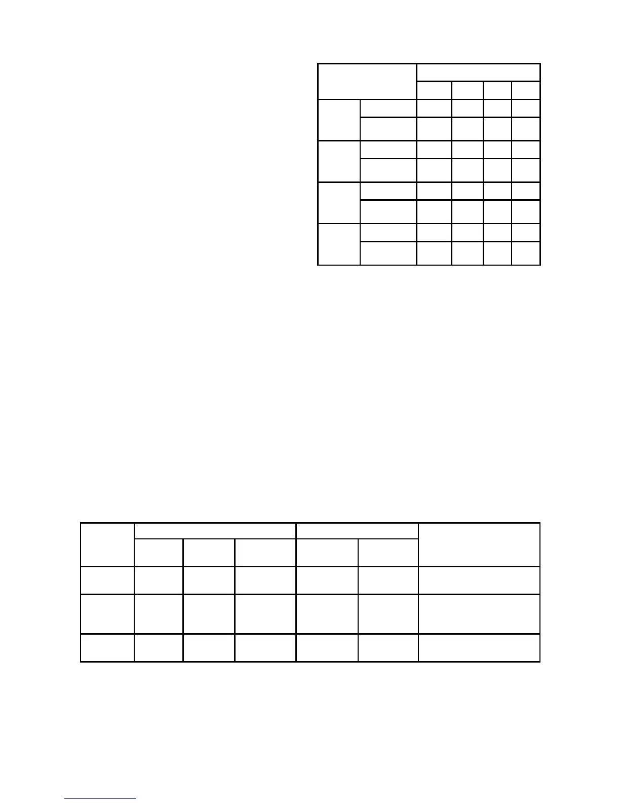
Table 6 indicates the typical window glass
temperature rise for various heater setting and
ambient temperature combinations.
NOTE
Higher heater settings reduce or eliminate
moisture buildup on the window, thereby
providing optimum detector performance.
Table 6—Typical LS2000 Window Temperature Rise (Degrees C)
for Various Heater Settings and Ambient Temperatures
LS2000 Window
Temperature Rise (C)
AMBIENT TEMPERATURE
-55°C -40°C 0°C 25°C
30%
Heater
Setting
Receiver 5.1 5.3 4.5 3.0
Transmitter 4.2 4.1 4.2 3.0
50%
Heater
Setting
Receiver 7.2 6.8 7.0 5.0
Transmitter 5.3 5.2 5.3 3.6
70%
Heater
Setting
Receiver 9.8 9.1 7.5 7.1
Transmitter 7.8 6.6 5.1 3.8
100%
Heater
Setting
Receiver 15.8 14.9 8.6 7.3
Transmitter 13.3 10.6 5.9 4.5
Table 4—LS2000 Receiver Status Conditions
Status
4-20mA Output Relays
LED
LS2000
Default
Advanced
User
Dened
Fault Relay Alarm Relay
Warm up 1.0 1.0
Detection
Disabled
De-energized Disabled Yellow - Solid
Normal 4.0 to 20.5 4.0 to 20.5 4.0 to 20.5 Energized Enabled
Green - Solid = Normal
Red - Flashing = Low Alarm
Red - Solid = High Alarm
Zero
Calibration
1.0 2.2 Configuration Energized Disabled Yellow - Flashing @ 5 Hz
Note: When the Communication Link is used, the transmitter LED operation matches receiver LED operation,
including alarm status.