2.2 95-871418
REPLACING AN EXISTING MODEL OPECL
WITH AN LS2000
Flat Surface Mount
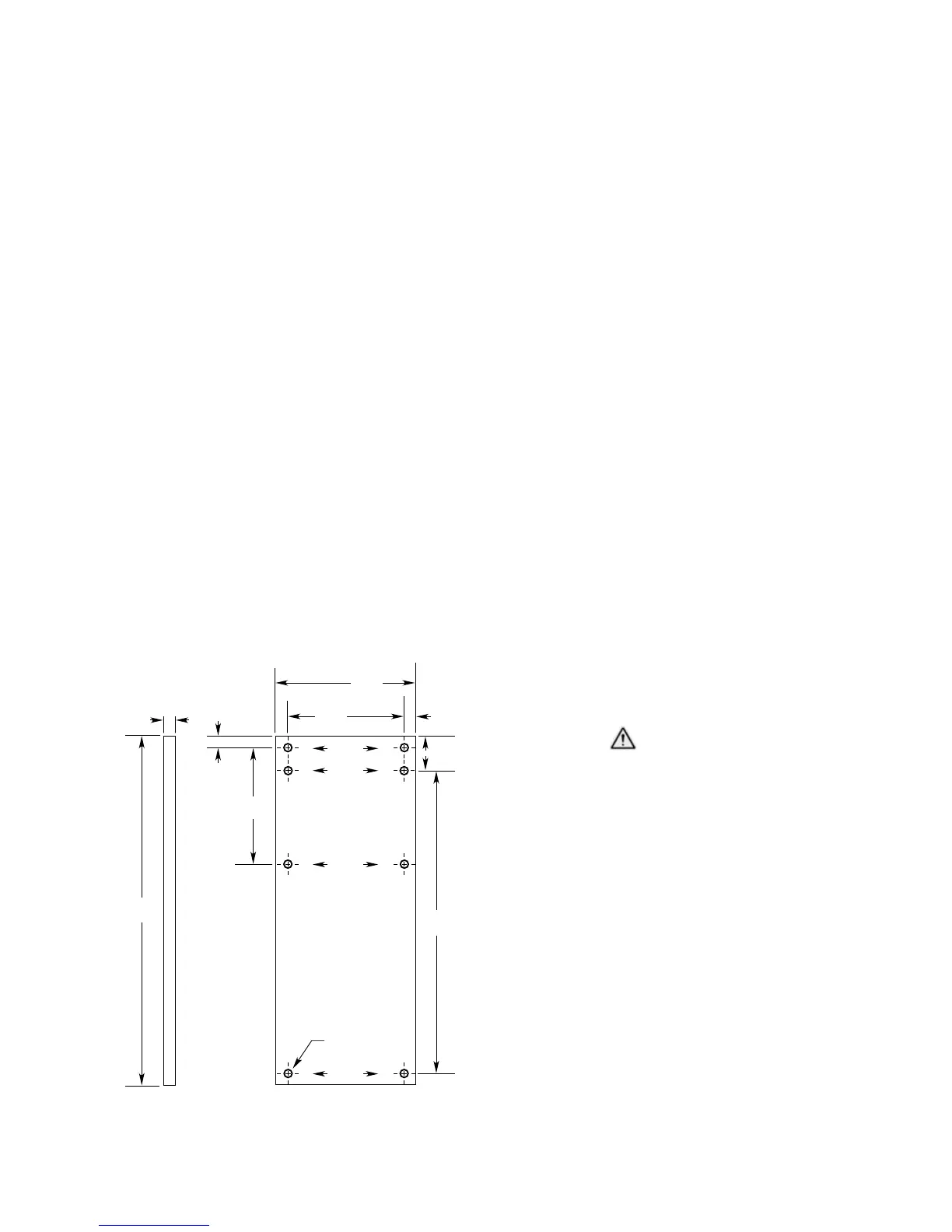
An optional adapter plate (part number 012718-
002) is available for converting an existing
OPECL flat surface mount to an LS2000 flat
surface mount without drilling new holes. See
Figure 9 for dimensions. The mounted LS2000
will have the following offsets compared to the
OPECL detector (when looking straight at the
wall/beam).
Left/right = 0”
Up/down = 0”
In/out = 0.3” closer to the wall/beam for the
LS2000.
Pole Mount
The LS2000 can be mounted to the same
pole as the Model OPECL using U-bolts. The
LS2000 will have the following offsets compared
to the OPECL detector.
Left/right = 0”
Up/down = 0” if the top U-bolt for the LS2000
is mounted 1” lower than the top U-bolt of the
OPECL detector.
In/out = 0.8” closer to the pole for the LS2000.
24 VDC POWER SUPPLY REQUIREMENTS
Calculate the total gas detection system power
consumption rate in watts from cold start-up.
Select a power supply with adequate capability
for the calculated load. Ensure that the selected
power supply provides regulated and filtered 24
Vdc power for the entire system. If a back-up
power system is required, a float-type battery
charging system is recommended. If an existing
source of 24 Vdc power is being utilized, verify
that system requirements are met.
NOTE
If disconnection of power is required,
separate disconnect capability must be
provided.
WIRING CABLE REQUIREMENTS
Always use proper cabling type and diameter
for input power as well as output signal wiring.
14 to 18 AWG (2.5 to 1.0 mm
2
) shielded stranded
copper wire is recommended.
Always install a properly sized master power
fuse or breaker on the system power circuit.
NOTE
The use of shielded cable in conduit
or shielded armored cable is required
for ATEX conformance. In applications
where the wiring is installed in conduit,
dedicated conduit is recommended.
Avoid low frequency, high voltage, and
non-signaling conductors to prevent
nuisance EMI problems.
CAUTION
The use of proper conduit installation
techniques, breathers, glands, and seals is
required to prevent water ingress and/or
maintain the explosion-proof rating.
POWER WIRING SIZE AND MAXIMUM
LENGTH
1. To ensure proper operation, LS2000 power
terminals and 4-20 mA terminals must receive
18 Vdc minimum. 24 Vdc is recommended.
2. Always determine voltage drops that will
occur to ensure that 24 Vdc is delivered to the
LS2000.
3. Normally, nothing smaller than 18 AWG (1.0
mm
2
) is recommended by Det-Tronics for
LS2000 power cabling.
Wire size requirements are dependent upon
power supply voltage and wire length.
2X 1.49
(3.78)
2X 13.0
(33.02)
4X 5.0
(12.7)
6.0
(15.24)
4X 0.5
(1.27)
2X 5.0
(12.7
)
2X 0.5
(1.27)
15.0
(38.1)
0.5
(1.27)
8X 3/8-16 UNC THRU
LS2000
OPECL
LS2000
OPECL
A2668
Figure 9—Dimensions of 012718-002 Flat Surface
Mounting Plate in Inches (cm)