2.2 95-871426
Procedure for System Commissioning
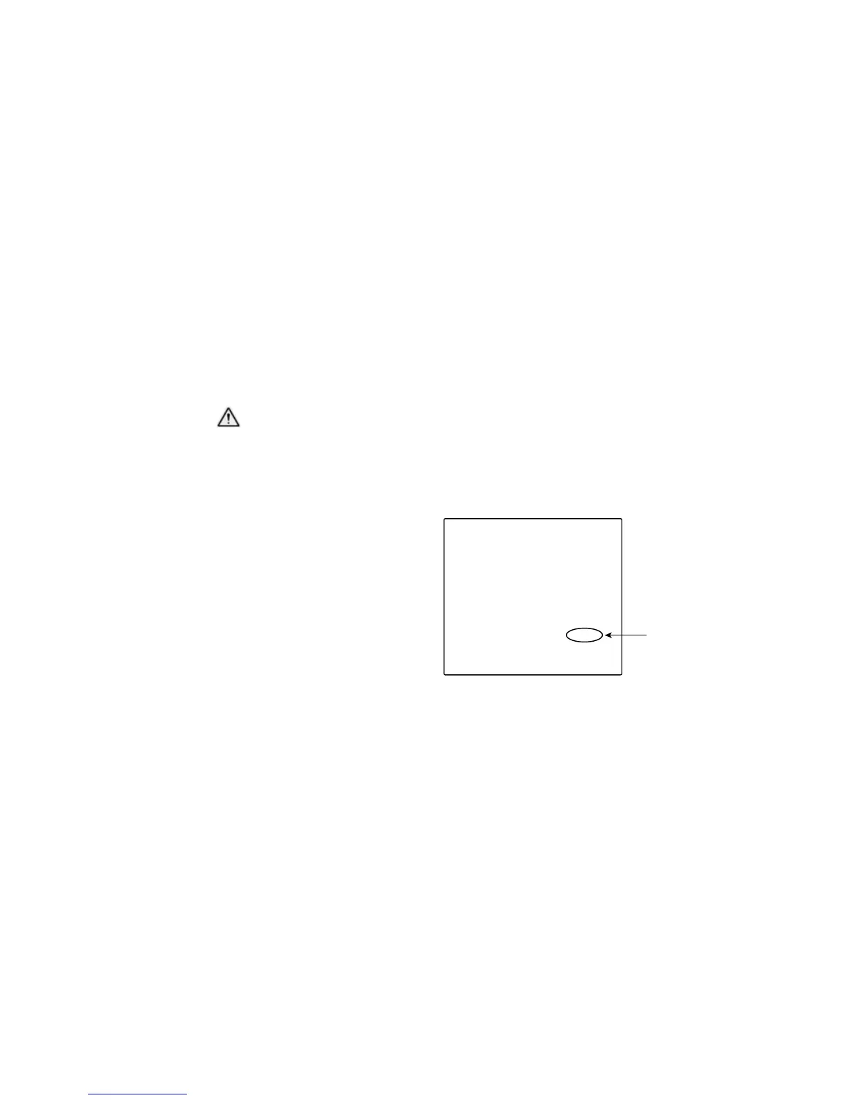
Using the Aperture
1. Align the LS2000 system using the Basic
Alignment procedure. At the completion
of this alignment, the output signal at the
receiver may indicate a fault condition as a
result of signal saturation.
2.
Attach the aperture to the front of the
LS2000
transmitter module using the captive screws
provided. For best weather protection, the
aperture hole should be located at the top of
the unit.
3.
Perform a zero calibration. After performing
the zero calibration, the receiver module
should display a normal condition (green LED)
and a steady 4 mA output.
RECOMMENDATIONS FOR USING THE
HART FIELD COMMUNICATOR
WARNING
The LS2000 does not use Intrinsically
Safe circuitry for connection to the HART
475 Communicator. Connecting a HART
475 Communicator to the LS2000 may
invalidate the Intrinsic Safety circuits of the
HART 475 Communicator.
• The HART communication device must
include the LS2000 device descriptor
(DD) software menu. The use of HART
communication devices without the proper
DDs may establish generic mode HART
communication, but will not enable proper
operation with LS2000. Refer to the HART
Appendix for additional information.
• Aminimumlevelofunderstandingwithregard
to the operation and navigation of the HART
communicator is required. Please refer to the
appropriate HART communicator instruction
manual for basic operating instructions if
required. Additional information on the use of
the HART communicator is provided within the
HART Appendix in this document.
• ForproperHARTcommunicationtooccur,itis
required that a 250-500 ohm resistive load be
present in the LS2000 analog 4-20 mA signal
loop output. See “Wiring Procedure” in the
INSTALLATION section.
GAIN LEVEL CHECK (Optional)
It is necessary to complete the alignment
procedure before checking the gain level.
HART or MODBUS communication is required to
check the gain.
Procedure
1. Connect the handheld HART communicator
to the receiver module’s 4-20 mA circuit.
2. Turn on the HART communicator and check
for LS2000 device recognition. When HART
communication is established, the LS2000
Online menu will be displayed on the
communicator display.
3. From the Online menu, select the Detector
Status menu (selection #2).
4. From the Detector Status menu, select the
Sensor Info menu (selection #3).
5. The Sensor Info menu will display the
following screen. Observe the Gas Mode
level indicated on the Sensor Info screen.
Sensor Info
1) Active last flash xxxxx
2) Reference last flash xxxxx
3) Active avg xxxxx
4) Ref avg xxxxx
5) Active normalized xx
6) Reference normalized xx
7) Ratio x.xx
8) Absorption x.xx
9) Gain xxxxx
Gain Mode xxxxx
Flash counts xxxx
Device Temp x.xx deg C
Tx lamp voltage xxxx
Gas Gain number