2.2 95-871424
6. Install the Alignment Tool onto the receiver
module by inserting the captive thumbscrews
into the threaded holes on the faceplate. See
Figure 22. Ensure that the alignment tool
is properly attached, that the eyepiece is
accessible, and that the thumbscrews are
completely tightened.
7. Using the Horizontal and Vertical Adjustment
Bolts, adjust the receiver module as required
until the cross hairs are centered as close
as possible to dead center on the window of
the transmitter module. Do not tighten the
adjustment bolts at this time, just snug down
all adjustment bolts finger tight.
8. Slightly loosen the Vertical Adjustment Bolts
so that tightening the 4 Horizontal Locking
Bolts does not cause the Detector Mounting
Assembly to bind as it is being pulled up.
9. Tighten the 4 Horizontal Locking Bolts in an
opposing-alternating pattern. Torque each
bolt to 200 in-lbs(22.6N•m)maximum.
10.
Tighten the Horizontal Adjustment Bolts to
200
in-lbs (22.6 N•m) maximum,
being careful to
tighten each bolt evenly against each other
to prevent torquing of the Detector Mounting
Assembly. Tighten the Locking nuts to
200
in-lbs (22.6 N•m) maximum
. The mounting
and alignment bracket is now secured
horizontally.
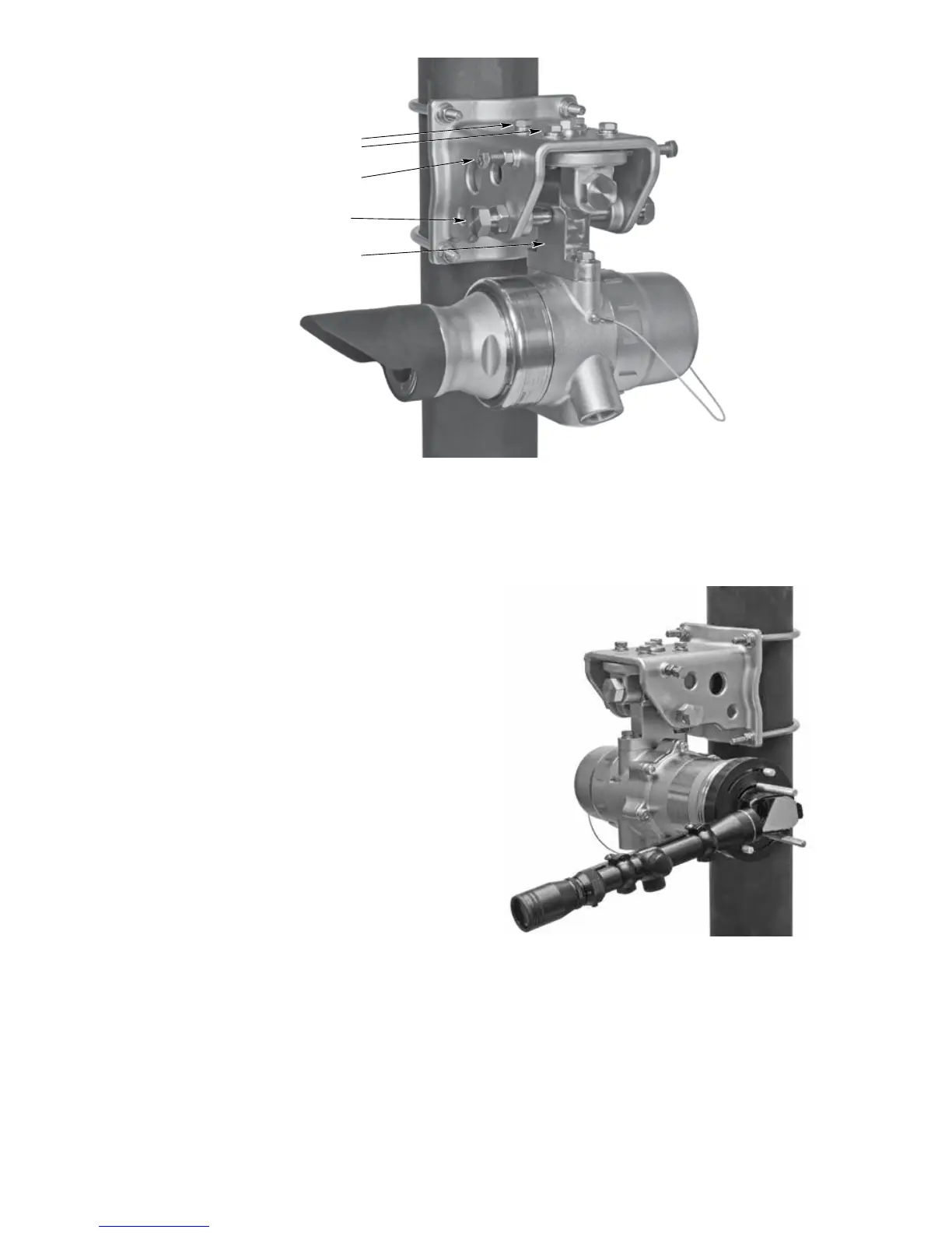
HORIZONTAL LOCKING BOLTS (4)
HORIZONTAL ADJUSTMENT BOLT
WITH LOCK NUT (2)
VERTICAL ADJUSTMENT BOLT
WITH LOCK NUT (2)
DETECTOR MOUNTING ASSEMBLY
Figure 21—LS2000 Mounting and Alignment Bracket (Receiver Module Shown)
Figure 22— LS2000 with Alignment Tool Installed