2
26 413 0
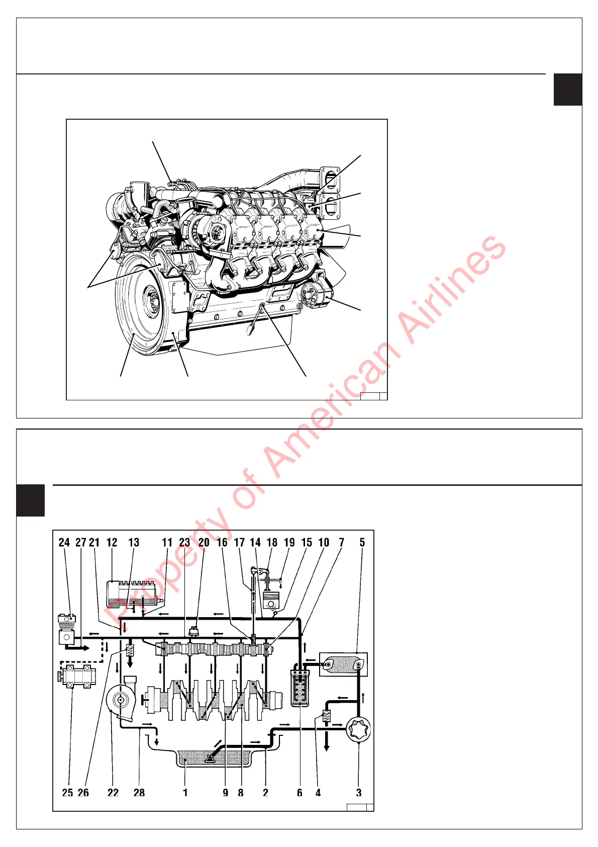
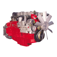
2.2.4 Cyl. Bank B – BF8M 1015
14 Flame-type heater plug system (A-side)
15 Oil filler neck
16 Cylinder head
17 Alternator
18 Oil dipstick
19 SAE housing
20 Flywheel
21 Compressor
22 Fuel connecting line
2.2 Engine Illustration Description of Engine
14
15
16
17
181920
21
22
2
26 394 0
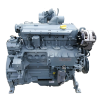
2.3.1 Lube Oil Circuit Schematic 1015
Wet Sump Lubrication
1 Oil pan
2 Intake pipe
3 Oil pump
4 Overpressure relief valve
5 Oil cooler
6 Spin-on oil filter
7 Main oil bores
8 Main bearing
9 Big-end bearing
10 Camshaft bearing
11 Oil supply to injection pump
12 Injection pump
13 Return line from injection pump to
crankcase
14 Line to spray nozzle
15 Spray nozzle with pressure-holding valve for
piston cooling
16 Tappet with control groove for pulse
lubrication of rocker arms
17 Pushrod, oil supply to rocker arm lubrication
18 Rocker arm
19 Oil return bore in cylinder head to crankcase.
20 Oil pressure sensor / oil pressure switch
21 Oil line to exhaust turbocharger
22 Exhaust turbocharger
23 Oil line to compressor (hydr. pump)
24 Compressor
25 Hydraulic pump
26 Pressure-holding valve (adjustable)
27 Oil return line from compressor (hydr.
pump) to crankcase
28 Oil return line from turbocharger to
Description of Engine 2.3 Lube Oil Circuit
Property of American Airlines