dS2824
dS2824 User Manual v4.12
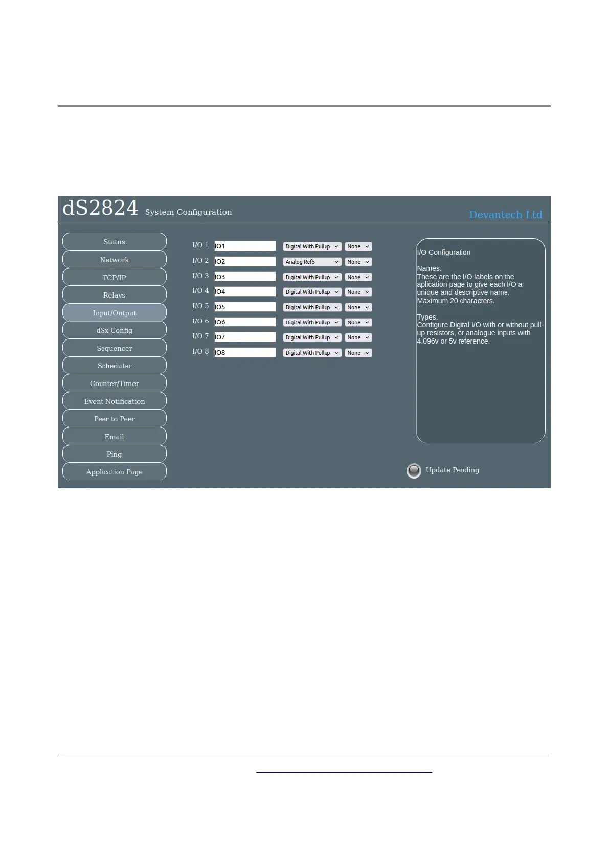
Input/Output configuration
The I/O Names tab is used to assign meaningful names to the I/O terminals.
As with relay names these may be up to 20 characters long, but do check it looks ok on a mo-
bile device or whatever you are using to control the module.
Click on the drop down box selection tab to select the I/O type.
The two digital modes are the same except for “Digital No-Pullup” the passive pull-up resistor
is turned off and for “Digital With Pullup” it is turned on.
The no-pullup option is useful for connecting to digital circuits (3.3v or 5v) that supply the in-
put voltage. The with pullup option turns on a weak pull up to 12v (actually nearer 7-8v be-
cause of the input design). This is useful for directly connecting volt free contacts such as relay
contacts or switches. They are connected between the pin (P) and ground (0v).
To use as inputs, make sure the output drive is off or the NPN transistor will drive the output
low. The NPN transistor can sink about 100mA.
The analogue modes convert the input volts to a digital number in the range 0-4095 (12-bit
conversion). The input voltage range is selectable for 4.096v (Analog Ref4) and 5v (Analog
Ref5).
Copyright © 2016-2021, Devantech Ltd.
All rights reserved.
www.robot-electronics.co.uk
21