dS2824
dS2824 User Manual v4.12
dSx Example
As an example, lets assume the following:
You need 2 dSx42 relay modules. You want relay 1 on one module to be controlled by input 2
from the other module using its analogue input. The dSx analogue inputs are 0-5v and use 10-
bit conversion, which is a range of 0-1023. You want the relay to turn on when the input goes
below 511 (about 2.5v) and off above that value.
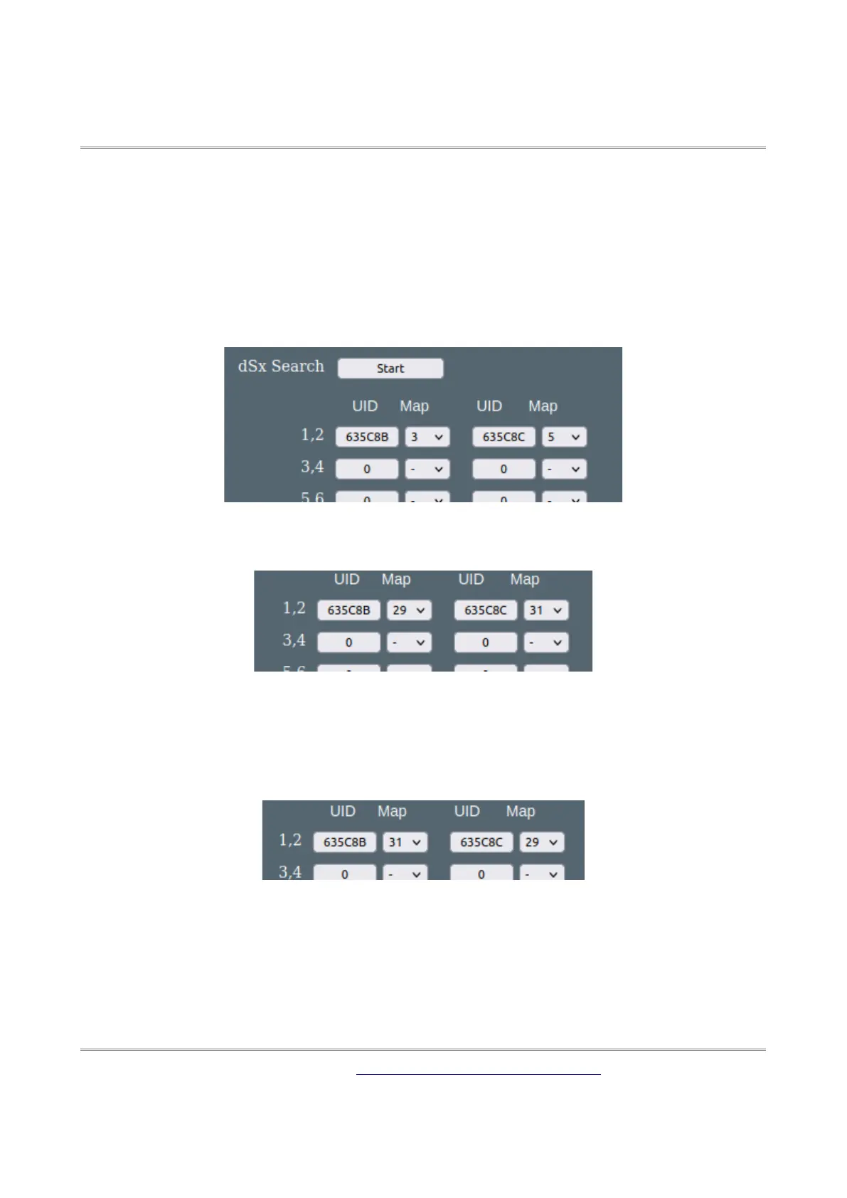
First connect your 2 dSx42 modules to the RS485 port and click “Start”. You should see the
two UID’s for your boards listed.
Next change the mapping as required to 29 for the first module and 31 for the other, using the
drop-down selection boxes.
Note: the UID’s are presented in ascending order, not any physical position on the RS485 bus,
so you will likely need to confirm which UID belongs to which module. Clicking the UID button
makes that module identify itself by flashing all its LEDs. Click again to stop.
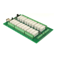
If you find its the module mapped to 29 that has the analogue input wired to it, swap them
over by changing the mapping like this:
You should always design your system by mapping number, not UID. That way if you ever need
to change a module you just make sure it has the same mapping as the original and your all
good to go. As part of your system documentation, record the mapping number against mod-
ule task so you can quickly restore the system should you need to.
Copyright © 2016-2021, Devantech Ltd.
All rights reserved.
www.robot-electronics.co.uk
26